Difference between revisions of "Plus Shield"
| (2 intermediate revisions by the same user not shown) | |||
| Line 1: | Line 1: | ||
=='''Introduction'''== | =='''Introduction'''== | ||
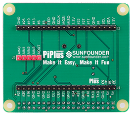
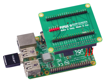
Plus Shield helps lead out the 40 pins of Raspberry Pi 2 Module B or Raspberry Pi 1 Module B+ with screening print marks (BCM marks, see figure Plus Shield Pin Arrangement) at each pin. The shield integrates AD-DA chip and RTC chips, both of which use the I2C communication protocol and occupy no pins. For detailed materials of the chips, visit the WIKI section of our website www.sunfounder.com.<br> | Plus Shield helps lead out the 40 pins of Raspberry Pi 2 Module B or Raspberry Pi 1 Module B+ with screening print marks (BCM marks, see figure Plus Shield Pin Arrangement) at each pin. The shield integrates AD-DA chip and RTC chips, both of which use the I2C communication protocol and occupy no pins. For detailed materials of the chips, visit the WIKI section of our website www.sunfounder.com.<br> | ||
| − | + | [[File:Plus shield.png]] | |
| + | [[File:Pi plus shield0128.png]] | ||
| + | =='''Schematic'''== | ||
| + | [http://wiki.sunfounder.cc/images/c/cb/Plus_shield_v1.6.pdf Plus_shield_v1.6 schematic][[File:PDF.jpg]]<br> | ||
=='''Software Installation'''== | =='''Software Installation'''== | ||
Take the following procedures of installation step by step. | Take the following procedures of installation step by step. | ||
| Line 14: | Line 17: | ||
Select Advanced Options => '''SPI''' => '''<Yes>''' => '''<Ok>''' => '''<Yes>''' => '''<Ok>''' | Select Advanced Options => '''SPI''' => '''<Yes>''' => '''<Ok>''' => '''<Yes>''' => '''<Ok>''' | ||
Select '''<Finish>'''. Close raspi-config. <br> | Select '''<Finish>'''. Close raspi-config. <br> | ||
| − | If a message of rebooting appears, click '''<No>''. Before reboot, we still need to complete some configurations. | + | If a message of rebooting appears, click '''<No>'''. Before reboot, we still need to complete some configurations. |
| + | |||
===Step 2. Add SPI, I2C, 1-Wire and RTC kernel module to the /etc/modules list=== | ===Step 2. Add SPI, I2C, 1-Wire and RTC kernel module to the /etc/modules list=== | ||
Latest revision as of 02:39, 8 November 2017
Contents
- 1 Introduction
- 2 Schematic
- 3 Software Installation
- 3.1 Step 1. Enable I2C and SPI
- 3.2 Step 2. Add SPI, I2C, 1-Wire and RTC kernel module to the /etc/modules list
- 3.3 Step 3. Enable I2C, SPI and 1-Wire hardware interfaces
- 3.4 Step 4. Create DS1307 (device creation) at boot
- 3.5 Step 5. Install related software packages
- 3.6 Step 6. Download source code
- 3.7 Step 7. Install SunFounder_PiPlus package to your Raspberry Pi
- 4 Application
Introduction
Plus Shield helps lead out the 40 pins of Raspberry Pi 2 Module B or Raspberry Pi 1 Module B+ with screening print marks (BCM marks, see figure Plus Shield Pin Arrangement) at each pin. The shield integrates AD-DA chip and RTC chips, both of which use the I2C communication protocol and occupy no pins. For detailed materials of the chips, visit the WIKI section of our website www.sunfounder.com.


Schematic
Software Installation
Take the following procedures of installation step by step.
Step 1. Enable I2C and SPI
Run the command to open Raspberry Pi Software Configuration Tool (raspi-config)
sudo raspi-config
Enable I2C:
Select Advanced Options =>I2C => <Yes> => <Ok> => <Yes>
Enable SPI:
Select Advanced Options => SPI => <Yes> => <Ok> => <Yes> => <Ok>
Select <Finish>. Close raspi-config.
If a message of rebooting appears, click <No>. Before reboot, we still need to complete some configurations.
Step 2. Add SPI, I2C, 1-Wire and RTC kernel module to the /etc/modules list
Open /etc/modules
sudo nano /etc/modules
Add the following contents at the end of the file (but if one or more such lines already exist in the file, you do not need to repeat them; just make sure the following lines are included).
snd-bcm2835
spi_bcm2708
spidev
i2c-dev
w1-gpio
w1-therm
rtc-ds1307
Save and exit.
Step 3. Enable I2C, SPI and 1-Wire hardware interfaces
Open /boot/config.txt
sudo nano /boot/config.txt
Add the following contents at the end of the file.
dtparam=spi=on
dtparam=i2c_arm=on
dtoverlay=w1-gpio
Save and exit.
Step 4. Create DS1307 (device creation) at boot
Open /etc/rc.local
sudo nano /etc/rc.local
Add before the line exit 0:
# For Raspberry Pi 1
echo ds1307 0x68 > /sys/class/i2c-adapter/i2c-0/new_device

# For Raspberry Pi 2
echo ds1307 0x68 > /sys/class/i2c-adapter/i2c-1/new_device

exit 0
Save and exit.
sudo apt-get update
sudo apt-get upgrade
sudo apt-get install git i2c-tools python-smbus
Git is a code management software that you can use to obtain or update the code we provide. Or you may learn to use Git and GitHub so you can manage and share your code conveniently.
Now you can reboot.
sudo reboot
Step 6. Download source code
Clone the source code from our GitHub page:
cd ~git clone https://github.com/sunfounder/SunFounder_PiPlus
Step 7. Install SunFounder_PiPlus package to your Raspberry Pi
Run setup.py to install
cd SunFounder_PiPlus
sudo python setup.py install –c
Add –c at the end, so after the SunFounder_PiPlus package is installed, you can set the time for DS1307.Also you can make the setting anytime by running ds1307setup.py.
sudo python ds1307setup.py
Then follow the guide to complete the setting of ds1307 time.
Application
There are two chips on the Plus Shield: DS1307 and PCF8591.
DS1307
First, check whether the time of DS1307 is correct:
sudo hwclock –r
If it goes wrong, change directory to SunFounder_PiPlus/ and run ds1307setup.py to modify the time.
cd ~/SunFounder_PiPlus/
sudo python ds1307setup.py
Run the example:
cd ~/SunFounder_PiPlus/shield_example/
sudo python plus_ds1307.py
Then you can see the time printed on the screen. Open plus_ds1307.py with nano:
nano plus_ds1307.py
You can see the parameter of DS1307(clock) is HOUR12. You can restore the function get_split_datetime() to the 24-hour format.
You may check the application of the function under main() – comments after #.
'''
get_split_datetime(), get date, time seperatelyj
'''
#date, time = DT.get_split_datetime()
#print 'date:', date
#print 'time:', time
<pre>
Delete the mark # at the beginning of the three lines below and comment the part of '''DT.get_datetime()''', as shown below:
<pre>
def main():
	while True:
		'''
		get_datetime() return the output of 'hwclock -r'
		command
		'''
		#datetime = DT.get_datetime()
		#print datetime
		'''
		get_split_datetime(), get date, time seperatelyj
		'''
		date, time = DT.get_split_datetime()
		print 'date:', date
		print 'time:', time
Press Esc to exit. Type in the command wq. Save and exit.
Run plus_ds1307.py again
sudo python plus_ds1307.py
Then you can see the date and time printed separately on the screen.
PCF8591
PCF8591 is an AD-DA conversion chip that adopts I2C communication method. Its address is 0x27. Since a 3.3V is applied to the chip, when using the analog pins, please make sure the voltage is no larger than 3.3V.
Plug in an analog module (e.g. one of the modules in the SunFounder Sensor Kit for Raspberry Pi).
Run the example:
cd ~/SunFounder_PiPlus/shield_example/
sudo python plus_pcf8591.py
The values read of AIN0 and AIN3 will be printed on the screen, as well as the output value of AOUT.
Open plus_pcf8591.py with nano:
nano plus_pcf8591.py
In the setup() function, ADC = PCF8591() is to initialize the PCF8591 chip.
In the main() function, the function read_all() is to read all the four input analog values.
read(channel) is to read the analog value of a specific pin. Channel is the input pin among AIN0~AIN3 (can be defined in SunFounder_PiPlus.Shield), which can also be indicated by 0-3.
write(value) is to output the analog value which ranges from 0~255.
Now try to read a single analog value by read()!
Plug in a device that can output analog values. Modify the sketch and run:
sudo python plus_pcf8591.py