Difference between revisions of "Q250"
(→Featrues) |
(→5. Section Board and Power Cord Test) |
||
| (18 intermediate revisions by the same user not shown) | |||
| Line 7: | Line 7: | ||
=='''Featrues'''== | =='''Featrues'''== | ||
| − | * | + | *The Q250 quadcopter is tailored for hobbyists and beginners for FPV flying. |
*It is a X-Shape quadcopter, more flexible and efficient than the H-Shape. | *It is a X-Shape quadcopter, more flexible and efficient than the H-Shape. | ||
| Line 16: | Line 16: | ||
*The tutorial of the software debugging and the assembling videos of the aircraft are provided for you. | *The tutorial of the software debugging and the assembling videos of the aircraft are provided for you. | ||
| + | |||
| + | =='''Components Test Before Assembly'''== | ||
| + | It’s necessary to test all the main components such as battery, motors, ESCs, flight controller board, etc., before assembly, in case of disassembling the aircraft to test after assembly when you find it cannot work.<br> | ||
| + | ===1. Battery, Balance Charger and Power Adapter Test=== | ||
| + | |||
| + | [[File:xx1.png]]<br> | ||
| + | |||
| + | ====Test Operations:==== | ||
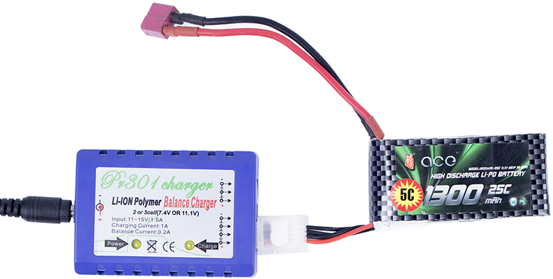
| + | 1. Connect the PR301 Li-ion Polymer Balance Charger (Power Charger) and 12V 1.5A Power Adapter, and plug the adapter to a socket. The power indicator on the balance charger will flash green, while the charging indicator orange (as shown in '''Figure 1-1'''). The charging indicator will dim one second later (as shown in '''Figure 1-2'''), meaning the connection works fine. <br> | ||
| + | |||
| + | [[File:ps1-1-1.png]][[File:ps1-2-2.png]]<br> | ||
| + | '''Figure 1-1 & Figure 1-2'''<br> | ||
| + | |||
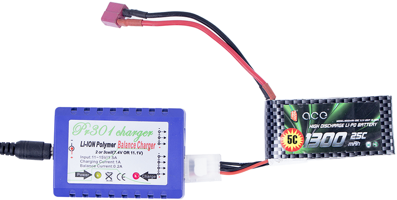
| + | 2. Connect the low-power 3S 11.1V 1300mAH T-Plug Li-Po Battery to the balance charger (DO NOT connect two or three batteries to charger at the same time); Then the charging indicator lights up in red ('''Figure 1-3'''), indicating it’s charging. <br> | ||
| + | |||
| + | [[File:ps1-3-3.png]]<br> | ||
| + | '''Figure 1-3'''<br> | ||
| + | |||
| + | 3. When the charging indicator turns from red to green ('''Figure 1-4'''), it means the battery is fully charged.<br> | ||
| + | |||
| + | [[File:ps1-4-4.png]]<br> | ||
| + | '''Figure 1-4'''<br> | ||
| + | |||
| + | ====Note:==== | ||
| + | 1. When you connect the balance charger to power, if the power indicator does not light up, it shows the charger is not well connected to power.<br> | ||
| + | 2. If the charging indicator does not light up after you connect the battery to charger, please check the connection, and whether the battery’s voltage is too low (<1.5V/CELL). If a cell is lower than 3V, the charger will provide low current recovery charging for 3 minutes; if it fails, the charging indicator will blink 0.5 seconds, indicating the battery is damaged. Only when each of all the cells reaches 3V, it will turn to normal charging. The charging Indicator will light up green when the battery is fully charged. Please take out the battery in time to avoid battery deformation or even explosion caused by overcharging.<br> | ||
| + | 3. The battery may fail to be charged because of over discharging, thus remember to mount a battery indicator alarm. When an alarm beeping is heard, please take out the battery to charge in time! You can try to recover the damaged battery if you have a stabilizator. Here's how to do:<br> | ||
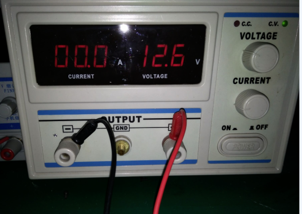
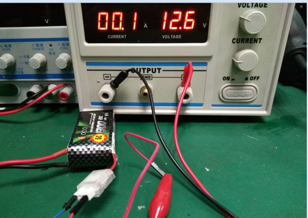
| + | 1). Adjust the output voltage to 12.6V as shown in '''Figure 1-5''';<br> | ||
| + | |||
| + | [[File:x9.png]]<br> | ||
| + | '''Figure 1-5''' <br> | ||
| + | |||
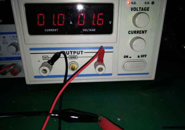
| + | 2). Connect the anode and cathode of the stabilizator directely, and adjust the current to 1A ('''Figure 1-6''');<br> | ||
| + | |||
| + | [[File:x10.png]]<br> | ||
| + | '''Figure 1-6''' <br> | ||
| + | |||
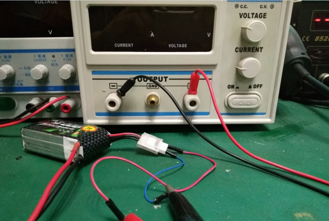
| + | 3). <font color="red">TURN OFF</font> the stabilizator, then connect the anode and cathode of the device to those of the battery ('''Figure 1-7''') - use two wires with different lengths to distinguish from each other so as to avoid short circuit by careless operation; <br> | ||
| + | |||
| + | [[File:x11.png]]<br> | ||
| + | '''Figure 1-7''' <br> | ||
| + | |||
| + | 4). Turn on the device to start the recovery. When the output current changes to 0 or almost 0, the recovery is done as shown in '''Figure 1-8'''.<br> | ||
| + | |||
| + | [[File:x12.png]]<br> | ||
| + | '''Figure 1-8''' <br> | ||
| + | |||
| + | ===2. Battery Indicator Alarm (with Buzzer) Test=== | ||
| + | |||
| + | [[File:x13.png]]<br> | ||
| + | |||
| + | ====Test Operations:==== | ||
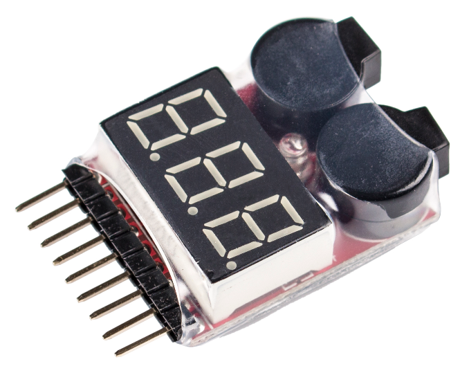
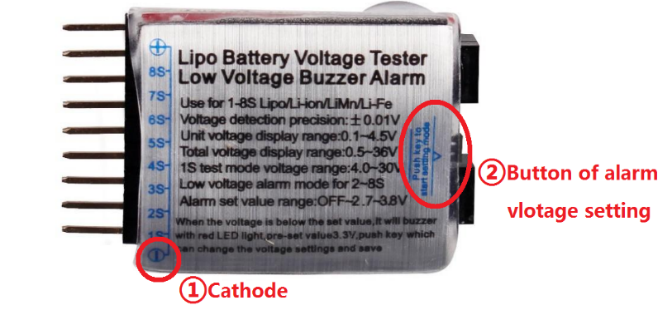
| + | 1.Check the back of the battery Indicator alarm, find the cathode pin marked with “-” (① of '''Figure 2-1''').<br> | ||
| + | 2. Connect the cathode of the Alarm to the first cathode hole of the battery charging cord and the rest pins to the corresponding headers as shown in '''Figure 2-2'''.<br> | ||
| + | 3.If they are connected correctly, the alarm will beep for three times, and then it will display the total voltage of all the cells and the voltage of each cell, in cycle. <br> | ||
| + | 4.The warning voltage threshold can be set by the button on the back of the alarm as shown in ② of '''Figure 2-1'''. Each press will add 0.1V and the setting will be saved automatically. The threshold value can be set to OFF (turn off alarm), or from 2.7V (default after manufactured) – 3.8V. You are recommended to set it to 3.7V.<br> | ||
| + | |||
| + | |||
| + | [[File:x14.png]]<br> | ||
| + | '''Figure 2-1''' <br> | ||
| + | <br> | ||
| + | [[File:ps2-2-2.png]]<br> | ||
| + | '''Figure 2-2''' <br> | ||
| + | |||
| + | ===3. Motors Test=== | ||
| + | |||
| + | [[File:Sj1.png]]<br> | ||
| + | |||
| + | ====Test Operations (power-off):==== | ||
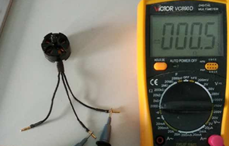
| + | 1. Test by multimeter: set the multimeter to the 200Ω setting to measure the direct-current resistance of the motors’ three-phrase winding - check two wires from three each time as shown below. The measured results of three times should be very close to each other. If the gap among the results is more than 10%, an inter-turn short circuit may have happened between the wires with the smallest result.<br> | ||
| + | |||
| + | [[File:sj2-2-2.png]][[File:sj3-3-3.png]][[File:sj4-4-4.png]]<br> | ||
| + | |||
| + | 2. Check the bearings and fans: when the rotator spins normally, there should have no noise, indicating the bearing and air gap is in good condition. If the bearing holds dead, the motor may burn out.<br> | ||
| + | |||
| + | ===4. ESCs Test=== | ||
| + | |||
| + | [[File:sj5.png]]<br> | ||
| + | |||
| + | ====Test Operations (power-on):==== | ||
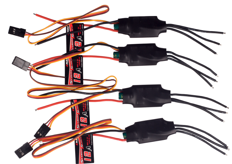
| + | 1. Ensure the receiver is in PWM mode. About shifting the receiver’s mode, please follow the instructions.<br> | ||
| + | 2. Connect the signal wire of the ESC to the pin 3 of the receiver, i.e., the yellow wire to pin S, red one to +, and black one to -.<br> | ||
| + | 3. Power on the radio transmitter → pull throttle to max → power on ESCs → detects a max throttle signal → beep twice, indicating the max throttle is set and saved → pull throttle to min within 2 seconds → a long beep indicates the min throttle signal is detected → check the battery’s voltage, beep three times, indicating the cells quantity of battery → hear the notes “♪ 1 2 3”, indicating it’s ready → pull up the throttle to start → pull up a little to see whether the motor spins or not.<br> | ||
| + | 4. Repeat the operations above to configure the rest motors and ESCs.<br> | ||
| + | '''Check the Test Video here:''' https://www.youtube.com/watch?v=3aV-8cS6D_I<br> | ||
| + | |||
| + | ===5. Section Board and Power Cord Test=== | ||
| + | |||
| + | [[File:Q250-1.png]]<br> | ||
| + | |||
| + | '''Test Operations:'''<br> | ||
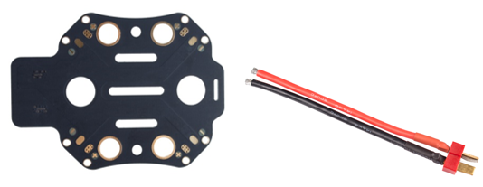
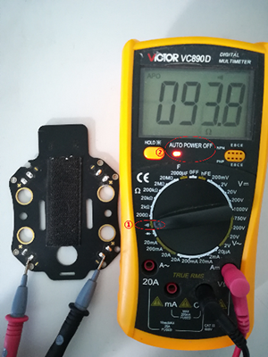
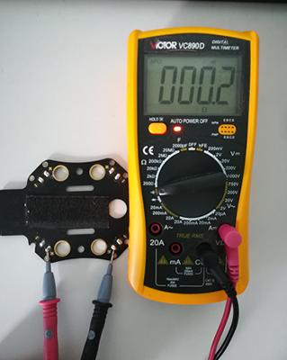
| + | 1. Test by multimeter: set the multimeter to Continuity mode (as shown in ① of '''Figure 5-1'''), check the conductivity of the adjacent “-” points on the Bottom Board (as shown in '''Figure 5-1'''), t he adjacent “+” points (as shown in '''Figure 5-2''')<br> | ||
| + | |||
| + | [[File:Q250-2.png]][[File:Q250-3.png]]<br> | ||
| + | '''Figure 5-1 & Figure 5-2'''<br> | ||
| + | |||
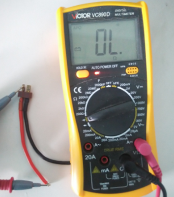
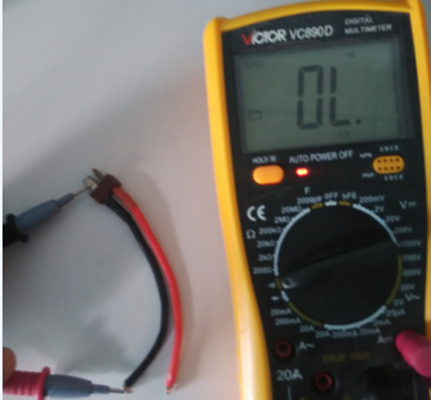
| + | and two ends of red and black wires in Male T-Plug Adapter Cable (100mm) ('''Figure 5-3''' and '''Figure 5-4''').<br> | ||
| + | |||
| + | [[File:Q250-4.png]][[File:Q250-5.png]]<br> | ||
| + | '''Figure 5-3 & Figure 5-4'''<br> | ||
| + | |||
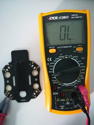
| + | Then check the shortcircuit between the “+” and “-” points ('''Figure 5-5'''), and the red wire and black one of the adapter cable ('''Figure 5-6'''). If a beep sounds and the red indicator lights up as shown in ② of '''Figure 5-1''', it means the circuit is open.<br> | ||
| + | |||
| + | [[File:Q250-6.jpg]][[File:Q250-7.png]]<br> | ||
| + | '''Figure 5-5 & Figure 5-6'''<br> | ||
| + | |||
| + | 2. Check the insulation of the adapter cable is broken or not. If there is a breakage on the cable, please wrap that area with an electrical tape to avoid accidents by short circuit.<br> | ||
| + | |||
| + | ===6. Flight Controller Board Test=== | ||
| + | |||
| + | [[File:sj13.png]]<br> | ||
| + | |||
| + | ====Test Operations:==== | ||
| + | When you power on the CC3D flight controller board, the power indicator (green) should light up constantly, while the status indicator (blue) should blink. If both indicators do not light up when you power it on, it proves the board is broken.<br> | ||
| + | If all the indicators works normally, then we should upgrade the firmware to further test the flight controller board. For details about how to operate, please refer to the user manual - '''CC3D Software Debugging'''.<br> | ||
=='''Technical Details'''== | =='''Technical Details'''== | ||
| Line 37: | Line 152: | ||
=='''Related links'''== | =='''Related links'''== | ||
| − | 1. | + | 1.Downlaod the the Ground Control Station (GCS) for the CC3D flight controller board: |
| − | <font color="blue">'''https://www.sunfounder.com/wiki/index.php?title=File:OpenPilot-RELEASE-15.02.02-win32.rar'''</font> | + | Windows:<font color="blue">'''https://www.sunfounder.com/wiki/index.php?title=File:OpenPilot-RELEASE-15.02.02-win32.rar'''</font><br> |
| + | Mac OS X:<font color="blue">'''https://www.sunfounder.com/wiki/index.php?title=File:Openpilot-release-13.06.04-osx.rar'''</font><br> | ||
| + | |||
| + | '''Note:OPENPILOT WAS DISCONTINUED!'''<br> | ||
| + | |||
| + | Use '''LibrePilot''' instead.<br> | ||
| + | For the latest version of LibrePilot, you can go here to download:<br> | ||
| + | http://opwiki.readthedocs.io/en/latest/user_manual/gcs_install_lp.html<br> | ||
2. For the assembling videos, please refer to this link: | 2. For the assembling videos, please refer to this link: | ||
| Line 47: | Line 169: | ||
3.For the remote control, you are recommended to refer to this link: | 3.For the remote control, you are recommended to refer to this link: | ||
| − | <font color="blue">'''https://www.sunfounder.com/rc.html'''</font> | + | <font color="blue">'''https://www.sunfounder.com/rc.html'''</font><br> |
| + | <font color="blue">'''https://www.sunfounder.com/drone/remote-controllers/flysky/flysky-fs-i6x-radio-system-transmitter.html'''</font> | ||
4.The Q250 quadcopter kit uses the 6040 propellers blades. If you want to experience a violent 3D flight, the 5045 propeller blades are needed. For them, you are recommended to refer to this link: | 4.The Q250 quadcopter kit uses the 6040 propellers blades. If you want to experience a violent 3D flight, the 5045 propeller blades are needed. For them, you are recommended to refer to this link: | ||
| − | <font color="blue">'''https://www.sunfounder.com | + | <font color="blue">'''https://www.sunfounder.com/5045propeller.html'''</font> |
5.For the camera kit, you are recommended to refer to this link: | 5.For the camera kit, you are recommended to refer to this link: | ||
| − | <font color="blue">'''https://www.sunfounder.com/drone/ | + | <font color="blue">'''https://www.sunfounder.com/drone/flight-camera/minicamera.html'''</font><br> |
| + | <font color="blue">'''https://www.sunfounder.com/drone/fpv-image-transceiver-kit-with-700tvl-hd-camera-mini-ts5823-32-channel-av-transmitter-5-8g-mushroom-antenna-for-quadcopter-multirotor-aircraft.html'''</font> | ||
| + | |||
| + | 6. For the FPV TFT LCD, you are recommended to refer to this link: | ||
| + | |||
| + | <font color="blue">'''https://www.sunfounder.com/drone/fpv-lcd.html'''</font> | ||
| + | |||
| + | 7. For the FPV Image Transceiver Kit, you are recommended to refer to this link: | ||
| + | |||
| + | <font color="blue">'''https://www.sunfounder.com/drone/fpv-image-transceiver-kit-with-700tvl-hd-camera-mini-ts5823-32-channel-av-transmitter-5-8g-mushroom-antenna-for-quadcopter-multirotor-aircraft.html'''</font> | ||
Latest revision as of 09:39, 3 May 2017
Contents
- 1 Introduction
- 2 Featrues
- 3 Components Test Before Assembly
- 4 Technical Details
- 5 Related links
Introduction
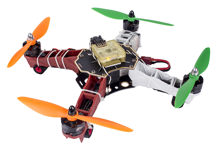
The realization of FPV flying starts from having a SunFounder Q250 aircraft. The SunFounder Q250 quadcopter is tailored for the hobbyists for FPV flying, featuring stability, flexibility and activity. You can realize a stable flight in a high or low altitude or in a forest with this aircraft. The skid landing damping sponge tubes bound onto the motors help stablize the flight and protect the frame through increasing the buffer between the frame and the land when the aircraft is landing.
It runs the OpenPilot firmware of the flight controller and the electronic speed controllers. This kit is designed to meet the hobbyists’ higher requirement of flying the aircraft. You can realize a stable flight in a small space or a rapid 3D flight based on your own configuration and parameter setting.
Featrues
- The Q250 quadcopter is tailored for hobbyists and beginners for FPV flying.
- It is a X-Shape quadcopter, more flexible and efficient than the H-Shape.
- It runs the firmware of CC3D flight controller, working with the EMAX 2204 motor and the Hobbywing ESC.
- Weight: 476 g ; Duration of flight: 11 minutes;Working voltage: 11.1V
- The tutorial of the software debugging and the assembling videos of the aircraft are provided for you.
Components Test Before Assembly
It’s necessary to test all the main components such as battery, motors, ESCs, flight controller board, etc., before assembly, in case of disassembling the aircraft to test after assembly when you find it cannot work.
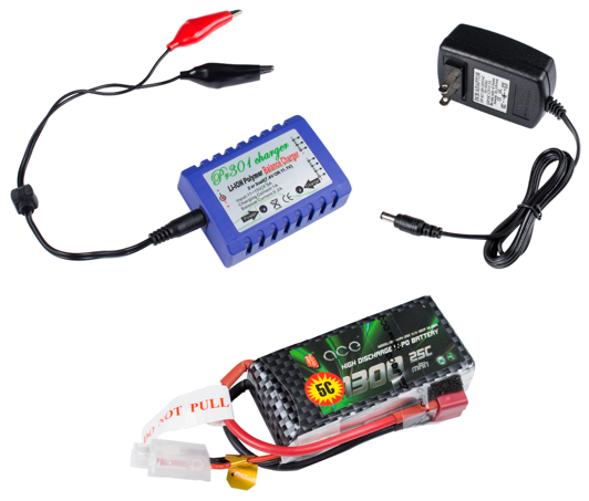
1. Battery, Balance Charger and Power Adapter Test
Test Operations:
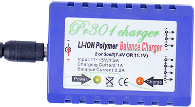
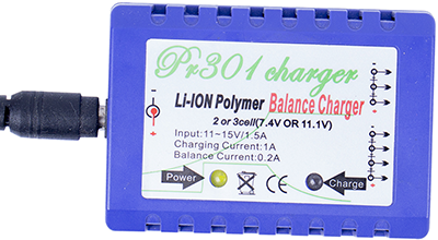
1. Connect the PR301 Li-ion Polymer Balance Charger (Power Charger) and 12V 1.5A Power Adapter, and plug the adapter to a socket. The power indicator on the balance charger will flash green, while the charging indicator orange (as shown in Figure 1-1). The charging indicator will dim one second later (as shown in Figure 1-2), meaning the connection works fine.
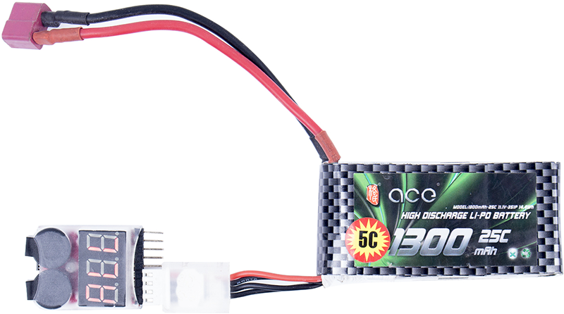
2. Connect the low-power 3S 11.1V 1300mAH T-Plug Li-Po Battery to the balance charger (DO NOT connect two or three batteries to charger at the same time); Then the charging indicator lights up in red (Figure 1-3), indicating it’s charging.
3. When the charging indicator turns from red to green (Figure 1-4), it means the battery is fully charged.
Note:
1. When you connect the balance charger to power, if the power indicator does not light up, it shows the charger is not well connected to power.
2. If the charging indicator does not light up after you connect the battery to charger, please check the connection, and whether the battery’s voltage is too low (<1.5V/CELL). If a cell is lower than 3V, the charger will provide low current recovery charging for 3 minutes; if it fails, the charging indicator will blink 0.5 seconds, indicating the battery is damaged. Only when each of all the cells reaches 3V, it will turn to normal charging. The charging Indicator will light up green when the battery is fully charged. Please take out the battery in time to avoid battery deformation or even explosion caused by overcharging.
3. The battery may fail to be charged because of over discharging, thus remember to mount a battery indicator alarm. When an alarm beeping is heard, please take out the battery to charge in time! You can try to recover the damaged battery if you have a stabilizator. Here's how to do:
1). Adjust the output voltage to 12.6V as shown in Figure 1-5;
2). Connect the anode and cathode of the stabilizator directely, and adjust the current to 1A (Figure 1-6);
3). TURN OFF the stabilizator, then connect the anode and cathode of the device to those of the battery (Figure 1-7) - use two wires with different lengths to distinguish from each other so as to avoid short circuit by careless operation;
4). Turn on the device to start the recovery. When the output current changes to 0 or almost 0, the recovery is done as shown in Figure 1-8.
2. Battery Indicator Alarm (with Buzzer) Test
Test Operations:
1.Check the back of the battery Indicator alarm, find the cathode pin marked with “-” (① of Figure 2-1).
2. Connect the cathode of the Alarm to the first cathode hole of the battery charging cord and the rest pins to the corresponding headers as shown in Figure 2-2.
3.If they are connected correctly, the alarm will beep for three times, and then it will display the total voltage of all the cells and the voltage of each cell, in cycle.
4.The warning voltage threshold can be set by the button on the back of the alarm as shown in ② of Figure 2-1. Each press will add 0.1V and the setting will be saved automatically. The threshold value can be set to OFF (turn off alarm), or from 2.7V (default after manufactured) – 3.8V. You are recommended to set it to 3.7V.
3. Motors Test
Test Operations (power-off):
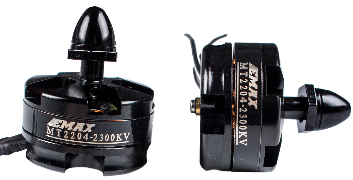
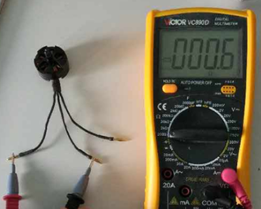
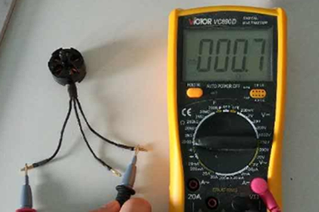
1. Test by multimeter: set the multimeter to the 200Ω setting to measure the direct-current resistance of the motors’ three-phrase winding - check two wires from three each time as shown below. The measured results of three times should be very close to each other. If the gap among the results is more than 10%, an inter-turn short circuit may have happened between the wires with the smallest result.
2. Check the bearings and fans: when the rotator spins normally, there should have no noise, indicating the bearing and air gap is in good condition. If the bearing holds dead, the motor may burn out.
4. ESCs Test
Test Operations (power-on):
1. Ensure the receiver is in PWM mode. About shifting the receiver’s mode, please follow the instructions.
2. Connect the signal wire of the ESC to the pin 3 of the receiver, i.e., the yellow wire to pin S, red one to +, and black one to -.
3. Power on the radio transmitter → pull throttle to max → power on ESCs → detects a max throttle signal → beep twice, indicating the max throttle is set and saved → pull throttle to min within 2 seconds → a long beep indicates the min throttle signal is detected → check the battery’s voltage, beep three times, indicating the cells quantity of battery → hear the notes “♪ 1 2 3”, indicating it’s ready → pull up the throttle to start → pull up a little to see whether the motor spins or not.
4. Repeat the operations above to configure the rest motors and ESCs.
Check the Test Video here: https://www.youtube.com/watch?v=3aV-8cS6D_I
5. Section Board and Power Cord Test
Test Operations:
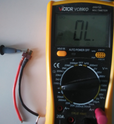
1. Test by multimeter: set the multimeter to Continuity mode (as shown in ① of Figure 5-1), check the conductivity of the adjacent “-” points on the Bottom Board (as shown in Figure 5-1), t he adjacent “+” points (as shown in Figure 5-2)
and two ends of red and black wires in Male T-Plug Adapter Cable (100mm) (Figure 5-3 and Figure 5-4).
Then check the shortcircuit between the “+” and “-” points (Figure 5-5), and the red wire and black one of the adapter cable (Figure 5-6). If a beep sounds and the red indicator lights up as shown in ② of Figure 5-1, it means the circuit is open.
2. Check the insulation of the adapter cable is broken or not. If there is a breakage on the cable, please wrap that area with an electrical tape to avoid accidents by short circuit.
6. Flight Controller Board Test
Test Operations:
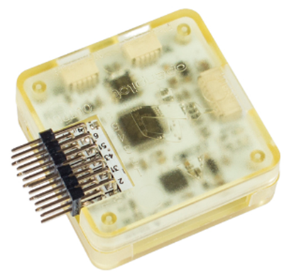
When you power on the CC3D flight controller board, the power indicator (green) should light up constantly, while the status indicator (blue) should blink. If both indicators do not light up when you power it on, it proves the board is broken.
If all the indicators works normally, then we should upgrade the firmware to further test the flight controller board. For details about how to operate, please refer to the user manual - CC3D Software Debugging.
Technical Details
Duration of flight: 11 minutes.
Weight:476g
Axis distance:250mm
Motor:EMAX MT2204 2300KV
Working voltage:11.1V
Battery capacity: 1300mAH
Electronic Speed Controller:EMAX Simon 15A brushless , UBEC not included
Maximum power:150W
Maximum tension: 440g
Related links
1.Downlaod the the Ground Control Station (GCS) for the CC3D flight controller board:
Windows:https://www.sunfounder.com/wiki/index.php?title=File:OpenPilot-RELEASE-15.02.02-win32.rar
Mac OS X:https://www.sunfounder.com/wiki/index.php?title=File:Openpilot-release-13.06.04-osx.rar
Note:OPENPILOT WAS DISCONTINUED!
Use LibrePilot instead.
For the latest version of LibrePilot, you can go here to download:
http://opwiki.readthedocs.io/en/latest/user_manual/gcs_install_lp.html
2. For the assembling videos, please refer to this link:
https://www.sunfounder.com/video/category/?cat=38
3.For the remote control, you are recommended to refer to this link:
https://www.sunfounder.com/rc.html
https://www.sunfounder.com/drone/remote-controllers/flysky/flysky-fs-i6x-radio-system-transmitter.html
4.The Q250 quadcopter kit uses the 6040 propellers blades. If you want to experience a violent 3D flight, the 5045 propeller blades are needed. For them, you are recommended to refer to this link:
https://www.sunfounder.com/5045propeller.html
5.For the camera kit, you are recommended to refer to this link:
https://www.sunfounder.com/drone/flight-camera/minicamera.html
https://www.sunfounder.com/drone/fpv-image-transceiver-kit-with-700tvl-hd-camera-mini-ts5823-32-channel-av-transmitter-5-8g-mushroom-antenna-for-quadcopter-multirotor-aircraft.html
6. For the FPV TFT LCD, you are recommended to refer to this link:
https://www.sunfounder.com/drone/fpv-lcd.html
7. For the FPV Image Transceiver Kit, you are recommended to refer to this link:
