Difference between revisions of "Hall Sensor module"
(→Resources) |
|||
| Line 58: | Line 58: | ||
[https://www.sunfounder.com/learn/Sensor-Kit-v2-0-for-Arduino/lesson-3-switch-hall-sensor-sensor-kit-v2-0-for-arduino.html Switch Hall Test Experiment for Raspberry Pi][[File:LINK.jpg]]<br> | [https://www.sunfounder.com/learn/Sensor-Kit-v2-0-for-Arduino/lesson-3-switch-hall-sensor-sensor-kit-v2-0-for-arduino.html Switch Hall Test Experiment for Raspberry Pi][[File:LINK.jpg]]<br> | ||
[https://www.sunfounder.com/learn/sensor-kit-v2-0-for-raspberry-pi-b-plus/lesson-17-hall-sensor-sensor-kit-v2-0-for-b-plus.html Analog/Switch Hall Test Experiment for Raspberry Pi][[File:LINK.jpg]]<br> | [https://www.sunfounder.com/learn/sensor-kit-v2-0-for-raspberry-pi-b-plus/lesson-17-hall-sensor-sensor-kit-v2-0-for-b-plus.html Analog/Switch Hall Test Experiment for Raspberry Pi][[File:LINK.jpg]]<br> | ||
| − | [ | + | [http://wiki.sunfounder.cc/index.php?title=File:44e_switch_hall_datsheet.pdf 44e_switch_hall_datsheet][[File:PDF.jpg]]<br> |
| − | [ | + | [http://wiki.sunfounder.cc/index.php?title=File:49e_Linear_Hall_Datasheet.pdf 49e_Linear_Hall_Datasheet][[File:PDF.jpg]] |
Revision as of 07:27, 20 March 2017
Contents
[hide]overview
Based on the Hall Effect, a hall sensor is a one that varies its output voltage in response to a magnetic field. Hall sensors are used for proximity switching, positioning, speed detection, and current sensing applications.
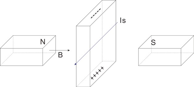
Hall Effect
The Hall effect is due to the nature of the current in a conductor. Current consists of the movement of many small charge carriers, typically electrons, holes, ions (see Electromigration) or all three. When a magnetic field is present, these charges experience a force, called the Lorentz force.[3] When such a magnetic field is absent, the charges follow approximately straight, 'line of sight' paths between collisions with impurities, phonons, etc. However, when a magnetic field with a perpendicular component is applied, their paths between collisions are curved so that moving charges accumulate on one face of the material. This leaves equal and opposite charges exposed on the other face, where there is a scarcity of mobile charges. The result is an asymmetric distribution of charge density across the Hall element, arising from a force that is perpendicular to both the 'line of sight' path and the applied magnetic field. The separation of charge establishes an electric field that opposes the migration of further charge, so a steady electrical potential is established for as long as the charge is flowing.

This phenomenon is Hall Effect.
Introduction
A hall sensor is a kind of magnetic field sensor based on the Hall Effect.
Electricity carried through a conductor will produce a magnetic field that varies with current, and a Hall sensor can be used to measure the current without interrupting the circuit. Typically, the sensor is integrated with a wound core or permanent magnet that surrounds the conductor to be measured.
Hall sensors can be categorized into Linear hall sensor and switch Hall sensors.
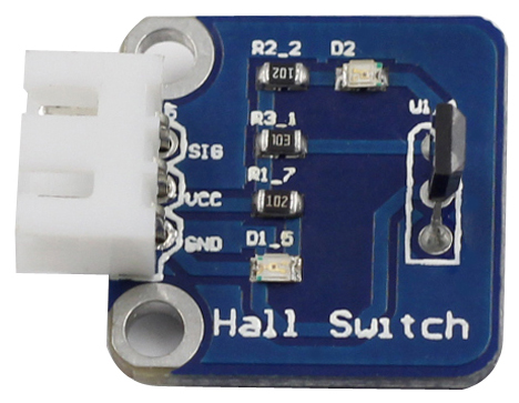
switch hall sensor
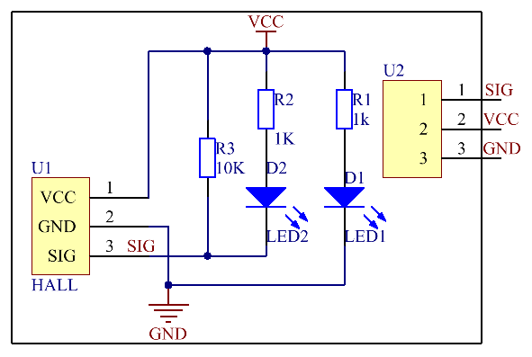
A switch Hall sensor consists of voltage regulator, Hall element, differential amplifier, Schmitt trigger, and output terminal and it outputs digital values.

See the following figure for the schematic diagram of the analog Hall switch sensor module.

Principles
When an energized conductor approaches the module, the output terminal SIG outputs low level; at the same time the corresponding LED lights up.
Features
1) Signals are output as long as there is a conductor cutting the magnet field.
2) High precision and good linearity , Adjustable sensitivity (accurate adjustment).With no contact, abrasion, shaking, or bound
3) Working voltage: 5V;PCB size: 2.0 x 2.0 cm
4) With power light and signal output indicator
5) Output digital signals, with a 3-pin anti-reverse cable included.
Application
The module can be applied to measurement of revolution, revolving speed, wind speed, flow speed, proximity switch, door lock notification device, alarm, auto-control circuit, etc.
analog hall sensor
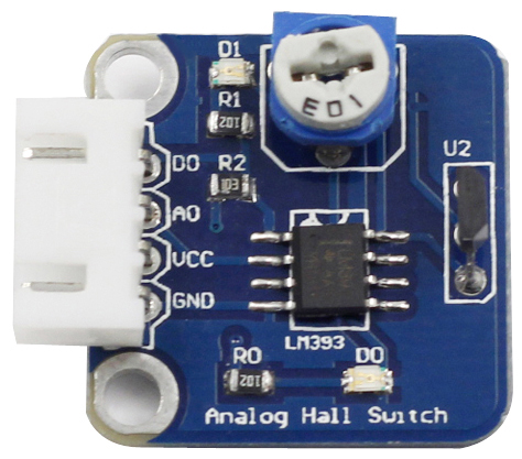
An Linear hall sensor consists of Hall element, linear amplifier, and emitter follower and it outputs analog values.If you add a comparator to Linear hall sensor it will be able to output both analog and digital signals.we call it as analog hall sensor .

See the following figure for the schematic diagram of the analog Hall switch sensor module.

Principles
when the sensor approaches the magnet, the value of pin A0 will change. When the value exceeds the threshold set by the potentiometer before, D0 outputs low level and the corresponding LED lights up.
Features
1) Signals are output as long as there is a conductor cutting the magnet field.
2) High precision and good linearity
3) Adjustable sensitivity (accurate adjustment)
4) Working voltage: 5V,PCB size: 2.3 x 2.3 cm
5) With power light and signal output indicator
Application
The module can be applied to measurement of some physical quantities such as displacement, current, etc.
Advantages
A Hall effect sensor may operate as an electronic switch.
• Such a switch costs less than a mechanical switch and is much more reliable.
• It can be operated up to 100 kHz.
• It does not suffer from contact bounce because a solid state switch with hysteresis is used rather than a mechanical contact.
• It will not be affected by environmental contaminants since the sensor is in a sealed package. Therefore it can be used under severe conditions
.
In the case of linear sensor (for the magnetic field strength measurements), a Hall effect sensor:
• can measure a wide range of magnetic fields
• is available that can measure either North or South pole magnetic fields
• can be flat
Resources
Analog Hall Test Experiment for Arduino![]()
Switch Hall Test Experiment for Raspberry Pi![]()
Analog/Switch Hall Test Experiment for Raspberry Pi![]()
44e_switch_hall_datsheet![]()
49e_Linear_Hall_Datasheet![]()