Difference between revisions of "NRF24L01 Wireless Transceiver Module"
| Line 5: | Line 5: | ||
<br> | <br> | ||
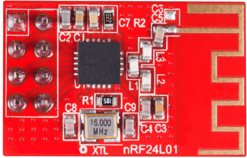
The pin functions of NRF24L01 are as shown:<br> | The pin functions of NRF24L01 are as shown:<br> | ||
| + | <br>[[File:Nrf-3.jpg]]<br> | ||
| + | |||
{|class="wikitable" | {|class="wikitable" | ||
|- | |- | ||
| Line 38: | Line 40: | ||
|MISO | |MISO | ||
|Master Input, Slave Output | |Master Input, Slave Output | ||
| + | |- | ||
|8 | |8 | ||
|IRQ | |IRQ | ||
| Line 44: | Line 47: | ||
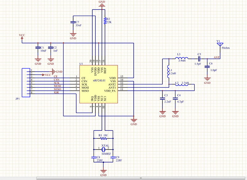
The schematic diagram of the module is shown as below:<br> | The schematic diagram of the module is shown as below:<br> | ||
| − | + | <br>[[File:Nrf-3.png]]<br> | |
==Features== | ==Features== | ||
1. nRF24L01+ is a single-chip radio transceiver for the worldwide 2.4-2.5 GHz ISM band, suitable for Arduino and Raspberry Pi.<br> | 1. nRF24L01+ is a single-chip radio transceiver for the worldwide 2.4-2.5 GHz ISM band, suitable for Arduino and Raspberry Pi.<br> | ||
| Line 84: | Line 87: | ||
|Not Connect | |Not Connect | ||
|} | |} | ||
| + | <br>[[File:Nrf-4.jpg]]<br><br> | ||
| − | '''Step 2. Compile''' | + | '''Step 2. Compile'''<br> |
Connect the SunFounder Uno R3 and the SunFounder Mega2560 to your computer, open two files under NRF24L01. For the SunFounder Mega2560, run the ''nrf_distance_test_RX.ino'' file; for the SunFounder Uno R3, run the ''nrf_distance_test_TX.ino'' file.<br> | Connect the SunFounder Uno R3 and the SunFounder Mega2560 to your computer, open two files under NRF24L01. For the SunFounder Mega2560, run the ''nrf_distance_test_RX.ino'' file; for the SunFounder Uno R3, run the ''nrf_distance_test_TX.ino'' file.<br> | ||
| − | '''Step 3. Test''' | + | '''Step 3. Test'''<br> |
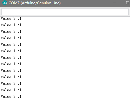
Open Serial Monitor on the IDE window for Mega2560, and you can see the received data printed, that is, Value 1 :1 Value 2 :1 | Open Serial Monitor on the IDE window for Mega2560, and you can see the received data printed, that is, Value 1 :1 Value 2 :1 | ||
| − | It indicates both NRF24L01 modules work. | + | It indicates both NRF24L01 modules work.<br> |
| − | + | <br>[[File:Nrf-5.png]]<br><br> | |
| − | Resource | + | ==Resource== |
| − | + | [https://www.sunfounder.com/wiki/images/e/ef/NRF24L01_test_code.rar '''''Test_code'''''][[File:Nrf-6.jpg]]<br> | |
| − | + | [https://www.sunfounder.com/wiki/images/8/86/NRF24L01.PDF '''''Datasheet'''''][[File:Nrf-7.jpg]] | |
Revision as of 08:16, 24 February 2017
Introduction
nRF24L01+ is a single-chip radio transceiver for the worldwide 2.4-2.5 GHz ISM band. The radio transmitters and receivers include frequency generator, enhanced ShockBurst mode controller, power amplifier, crystal oscillator modulator and demodulator. You can select the output power channel and protocol by setting through the SPI port. The current consumption for the nRF24L01+ is extremely low - under the transmitter mode, when the transmitting power is 0dBm, the current consumption is only 11.3mA; under the receiving mode, it is 13.5mA; under the power down and idle mode, the consumption is even lower. As for application, it's widely used in many devices such as wireless mouse and keyboard, game handle, remote control set, industry sensor,toys,etc.
The pin functions of NRF24L01 are as shown:
File:Nrf-3.jpg
| Pin | Name | Description |
| 1 | GND | Ground (0V) |
| 2 | VCC | Power Supply (3.3V) |
| 3 | CE | Mode Enable Activates RX or TX mode |
| 4 | CSN | Chip Select |
| 5 | SCK | Serial Clock |
| 6 | MOSI | Master Output, Slave Input |
| 7 | MISO | Master Input, Slave Output |
| 8 | IRQ | Interrupt Request. Under wireless communication, MCU communicates with NRF24L01 by IRQ |
The schematic diagram of the module is shown as below:

Features
1. nRF24L01+ is a single-chip radio transceiver for the worldwide 2.4-2.5 GHz ISM band, suitable for Arduino and Raspberry Pi.
2. Supports 6-channel receiving, with a transmission speed of up to 2Mbps.
3. Multi-frequency point: With 125 frequency points, it can meet multipoint communication and frequency hopping communication requirements.
4. Ultra-small: 24*15mm, with built-in 2.4GHz antenna.
5. Easy to develop: the link layer is fully integrated on the module, making it easy for development.
Test Experiment
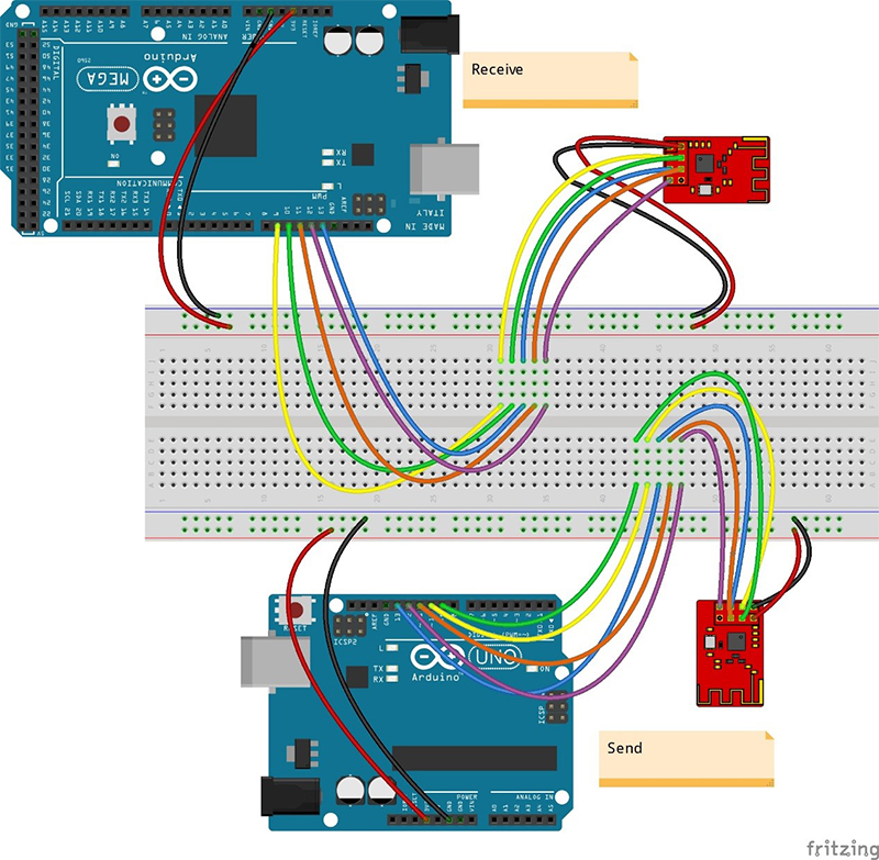
Step1. Wire
Wire the NRF24L01 to the SunFounder Uno board (the same to Mega2560) as follows.
| nRF24L01 Module | SunFounder Uno (SunFounder Mega2560) |
| GND | GND |
| VCC | 3.3V |
| CE | D9 |
| CSN | D10 |
| SCK | D13 |
| MOSI | D11 |
| MISO | D12 |
| IRQ | Not Connect |
Step 2. Compile
Connect the SunFounder Uno R3 and the SunFounder Mega2560 to your computer, open two files under NRF24L01. For the SunFounder Mega2560, run the nrf_distance_test_RX.ino file; for the SunFounder Uno R3, run the nrf_distance_test_TX.ino file.
Step 3. Test
Open Serial Monitor on the IDE window for Mega2560, and you can see the received data printed, that is, Value 1 :1 Value 2 :1
It indicates both NRF24L01 modules work.


