Difference between revisions of "Ultrasonic Module"
(→Resource) |
(→Introduction) |
||
| Line 1: | Line 1: | ||
=='''Introduction'''== | =='''Introduction'''== | ||
| − | <font color="blue">An upgraded ultrasonic module – improved properties and performance in various aspects</font> | + | <font color="blue">An upgraded ultrasonic module – improved properties and performance in various aspects</font><br> |
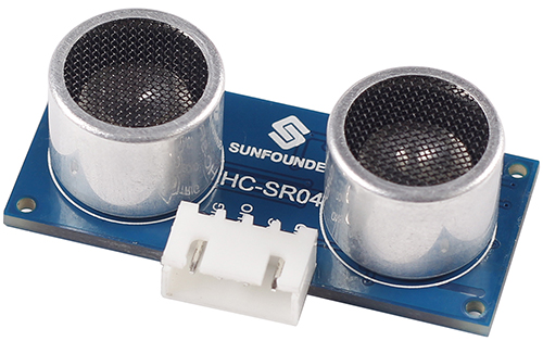
[[File:Ultrasonic .jpg]] <br> | [[File:Ultrasonic .jpg]] <br> | ||
Ultrasonic ranging module HC - SR04 provides 2cm - 700cm non-contact measurement function, the ranging accuracy can reach to 3mm. The modules includes ultrasonic transmitters, receiver and control circuit. The basic principle of work: <br> | Ultrasonic ranging module HC - SR04 provides 2cm - 700cm non-contact measurement function, the ranging accuracy can reach to 3mm. The modules includes ultrasonic transmitters, receiver and control circuit. The basic principle of work: <br> | ||
| Line 6: | Line 6: | ||
(2) The Module automatically sends eight 40 kHz and detect whether there is a pulse signal back. <br> | (2) The Module automatically sends eight 40 kHz and detect whether there is a pulse signal back. <br> | ||
(3) IF the signal back, through high level , time of high output IO duration is the time from sending ultrasonic to returning. Test distance = (high level time×velocity of sound (340M/S) / 2. | (3) IF the signal back, through high level , time of high output IO duration is the time from sending ultrasonic to returning. Test distance = (high level time×velocity of sound (340M/S) / 2. | ||
| + | |||
=='''Pin Function'''== | =='''Pin Function'''== | ||
'''TRIG''': Trigger Pulse Input<br> | '''TRIG''': Trigger Pulse Input<br> | ||
Revision as of 04:01, 31 March 2016
Contents
[hide]Introduction
An upgraded ultrasonic module – improved properties and performance in various aspects

Ultrasonic ranging module HC - SR04 provides 2cm - 700cm non-contact measurement function, the ranging accuracy can reach to 3mm. The modules includes ultrasonic transmitters, receiver and control circuit. The basic principle of work:
(1) Using IO trigger for at least 10us high level signal;
(2) The Module automatically sends eight 40 kHz and detect whether there is a pulse signal back.
(3) IF the signal back, through high level , time of high output IO duration is the time from sending ultrasonic to returning. Test distance = (high level time×velocity of sound (340M/S) / 2.
Pin Function
TRIG: Trigger Pulse Input
ECHO: Echo Pulse Output
GND: Ground
VCC: 5V Supply
Features
| Working Voltage | DC5V |
| Working Current | 16mA |
| Working Frequency | 40Hz |
| Max Range | 700cm, Ensured stable signal within 5m, gradually faded signal outside 5m till disappearing at 7m position. |
| Min Range | 2cm |
| Trigger Input Signal | 10uS TTL pulse |
| Echo Output Signal | Input TTL lever signal and the range in proportion |
| Dimension | 46x20.5x15 mm |
Pricinple
The Timing diagram is shown below. You only need to supply a short 10uS pulse to the trigger input to start the ranging, and then the module will send out an 8 cycle burst of ultrasound at 40 kHz and raise its echo. The Echo is a distance object that is pulse width and the range in proportion .You can calculate the range through the time interval between sending trigger signal and receiving echo signal. Formula: uS / 58 = centimeters or uS / 148 =inch; or: the range = high level time * velocity (340M/S) / 2; we suggest to use over 60ms measurement cycle, in order to prevent trigger signal to the echo signal.

Note: If you want to test in a 500cm+ distance, you need to change the NewPing library, which defines the maximum distance (i.e. 500cm). You can set it as 700 or higher. it is as shown in follwing:
#define MAX_SENSOR_DISTANCE 710