SunFounder MARS Board
Contents
Overview
SunFounder Mars board is totally compatible with the official Arduino Uno board, with also ATMEGA328P as the processor, the same Optiboot bootloader as Uno. And it has 14 digital I/Os pins and 6 analog inputs and is featured with a 32KB program storage and 16MHz crystal oscillator and so on.
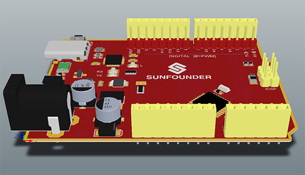
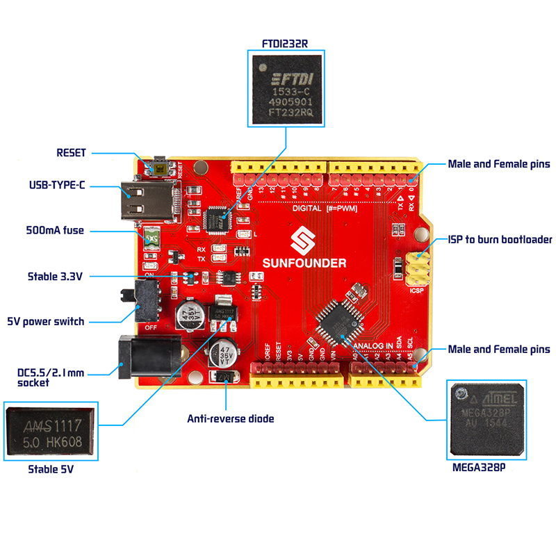
Multiple features make it unique: beautiful red PCB, parallel yellow and red pins, and a beautiful red appearance. In technology, it uses FTDI232R for USB-to-serial and adopts Type-C, the only USB port so far that supports reversible plug orientation. All the I/O ports are made with two pins (male and female) in a row, for free to use – you can just plug Dupont wires regardless of M or F.
A 5V power switch is added to control the board power, which may be expected by mass hobbyists – you can switch off the board when it's not in use, so as to avoid frequent plugging). In addition, a reset button is set at the board side for operational convenience. To save space, the ATmega328P microcontroller is packaged in patch.
Introduction
The SunFounder Mars is a microcontroller board based on the ATmega328P. It has 14 digital input/output pins (of which 6 can be used as PWM outputs), 6 analog inputs, a 16 MHz quartz crystal, a power switch, a USB connection, a power jack, an ICSP header and a reset button. It contains everything needed to support the microcontroller.
Power Types(USB Port/Jack)
Every Arduino board needs a way to be connected to a power source. You can power the Mars board by connecting it to your computer via a Type-C USB cable, or by an AC-to-DC adapter or battery. The jack supports a voltage range of 7-12V. Though you're not recommended to use as up to12V, because the adapter is AC to DC, a slight fault in the filter can cause the board to be burnt. You may consider our 9V adapter (on Amazon http://www.amazon.com/dp/B01ABTKHIO).
You can upload the code to the board via the USB cable.
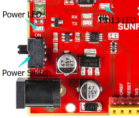
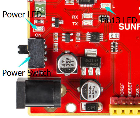
Speaking of power, there is a power switch which is unique among Arduino compatibles. After you've finished an experiment or want to take a break, just switch off the board – in the long term, USB plugging/unplugging can be reduced.
Pins (5V, 3.3V, GND, Analog, Digital, PWM, AREF)
The Mars board has pins of several functions, which is marked on the board.
GND: ground. There are multiple GND pins on Mars. They are connected with each other, so you can connect any of them in your circuit.
5V&3.3V: There are 5V and 3.3V voltage regulator chips on the board, thus able to supply 5V and 3.3V. You can choose which to use based on actual situations.
Analog pins: You can tell from the pin name A0-A5: A is short for analog. These pins can read values of analog sensors and convert them to digital ones which we can read. Note that pin A4 and A5 do more than that: A4(SDA), A5(SCL), SDA and SCL are I2C bus lines. When you need to connect to an I2C module, you may need to connect it with these two pins. All analog pins support I/O function and can be used as digital pins, though we don't usually do.
Digital pins: Pins 0-13 are digital pins. They can be used for digital input and output. Digital signals are only 0 and 1.
The name of some pins begins with a # (#3, #5, #6, etc.); they act as normal digital pins, but can also be used for something called Pulse-Width Modulation (PWM). The pins are similar to analog output ones. For example, making an RGB LED flash various colors (refer to the page under LEARN->Get Tutorials) is realized by changing the output value of the PWM pin to control LED colors.
The digital pins 0 and 1 can also be used as serial data sending and receiving ports, 0(RX) and 1(TX). Both have an indicator LED, which will blink when you're uploading sketches to Mars, meaning the board is communicating with your computer via serial interface.
RESET: To rerun the program. It is connected with the RESET button. Just press it down to reset the board.
IOREF: provides a reference voltage for digital I/O ports. Most of the time you can leave this pin alone.
AREF: provides a reference voltage for analog I/O ports. Most of the time you can leave this pin alone. It is sometimes used to set an external reference voltage (between 0V and 5V) as the upper limit for the analog input pins.
Features
- ATmega328P Microcontroller
- FTDI232R for USB-to-serial and Type-C USB Port
- Operating Voltage: 5V; Input Voltage: 7-12V (9V preferred)
- Parallel male and female I/O Pins
- 5V power switch to control the board power
- 14 digital I/Os Pins (6 ports support PWM output)
- 6 analog Inputs
- ICSP port for bootloader
- 32KB program storage (0.5KB for bootloader)
- 2KB RAM
- 1KB EEPROM
- 16 MHz crystal oscillator
- Output: 5V, 3.3V input compatible
- Compatible with all peripheral modules for Arduino Uno R3
- FTDI232R for USB-to-serial
- USB Type-C Port
Schematic
How to Use
Preparations
Type-C USB cable *1
SunFounder Mars Board * 1
PC * 1
Install Arduino Software (IDE)
If you haven't installed the Arduino Integrated Development Environment (IDE) yet, go to https://www.arduino.cc/en/Main/Software .
On the page, check the software list on the right side under Download the Arduino Software. Find the version that suits your operation system and click to download. For the details of installing steps, you can refer to the guide on Installing the Arduino IDE.
For Windows Users
For detailed installation, you can refer to the steps for Windows users in Installing Arduino IDE. It would be quite simple really: just download the zip package needed and unzip and then install step by step following the instructions.
Plug in the Mars Board
Connect the Mars board to your computer via a USB Type-C cable. Now you need to know whether the power switch is ON or OFF. Observe that if the green power indicator LED brightens and the LED connected to pin 13 blinks slowly, it means the switch is pushed at ON state. The USB connection with the PC is necessary to program the board and not just to power it up.
If you've downloaded the Windows Installer, when you plug the board into the computer, the system will install the driver automatically. After a while, there may appear a prompt message (some computers may not prompt), which means the driver is installed successfully.
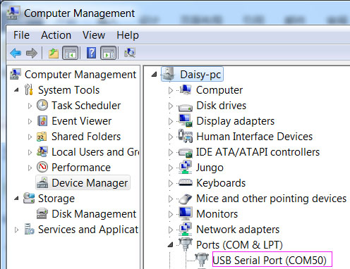
You can check the port which the board is connected to, by going to Device Manager -> Ports. Then you can see USB Serial Port (COMx) (x means the port number. E.g. In my computer it's COM50; but yours should be different). If this appears, it means your computer have recognized the board.
Open IDE
Double click the Arduino icon (arduino.exe) created by the installation process.
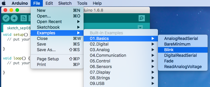
Then an empty IDE window will appear. Now open an example sketch (code file) to learn the basics. Select File > Examples >01.Basics > Blink.
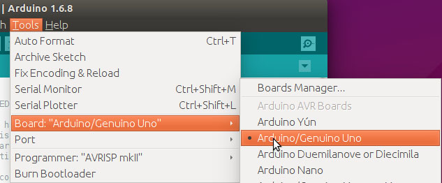
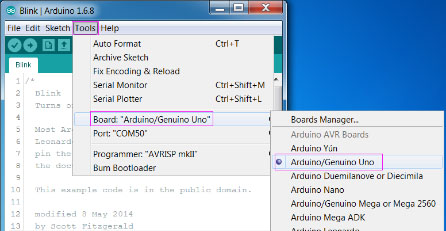
Then Tools ->Board->Arduino/Genuino Uno.
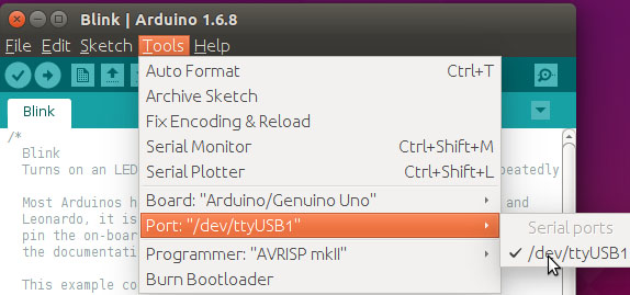
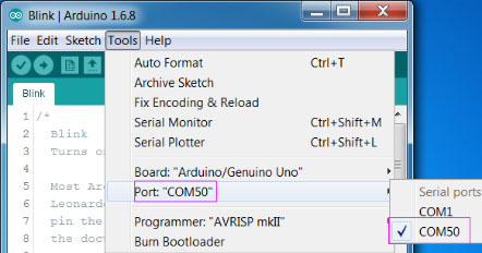
Then select Tools ->Port and select the port you just checked on Device Manager.
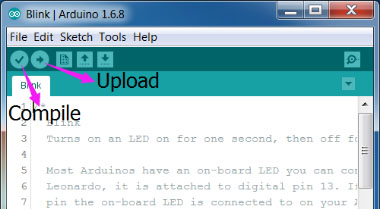
Click the Upload icon to upload the sketch to your board. And the icon Compile to compile sketches (usually used to refer to a code file), which always checks the code. Also when you click Upload, the code will be compiled. The sketches can be uploaded to the board when there is nothing wrong with them. Therefore, generally you just need to click Upload.
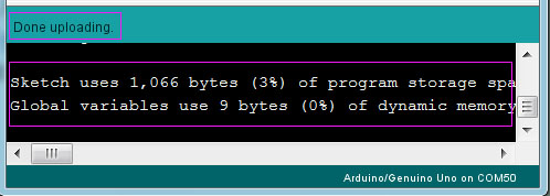
If "Done uploading" appears at the bottom of the window, it means the sketch has been successfully uploaded. And if you see the pin 13(L) LED starts to flicker, it means the code has been successfully run.
For more details about Arduino IDE, go to Arduino Software (IDE)
http://www.arduino.cc/en/Guide/Environment
If your sketch fails upload, go to Troubleshooting
http://www.arduino.cc/en/Guide/Troubleshooting
When the board is not used, push the power switch to OFF.
For Linux Users
It may be a little more complex to install IDE on Linux. Refer to the installation steps for Linux users on Installing Arduino IDE page mentioned previously.
Plug in the Mars Board
Connect the Mars board to your computer via a USB Type-C cable. Now you need to know whether the power switch is ON or OFF. Observe that if the green power indicator LED brightens and the LED connected to pin 13 blinks slowly, it means the switch is pushed at ON state. The USB connection with the PC is necessary to program the board and not just to power it up.
The serial port for Mars will be assigned by the computer.
Open the IDE
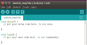
Double click the Arduino icon (arduino.exe) created by the installation process. Then an empty IDE window will appear.
Now open an example sketch (code file) to learn the basics. Select File > Examples. There are some built-in examples sketches included in the IDE. As a beginner, you can start from studying these examples.
Before uploading the code to your board, first you need to select the correct board. For example, select Adruino/Genuino Uno if you’re using an Uno board.
Then select Port. The port here (/dev/ttyUSB1) may be different from the Arduino board name (Uno, etc.).
Click the right arrow button to upload the sketch to the Arduino board. If "avrdude:ser_open():cann’t open device”/dev/ttyUSB1”:Permission denied" is prompted, you need the permission to open the serial port. Take the following steps.
Open a terminal and type in:
ls –l /dev/ttyUSB*
Then the following contents will appear:
crw-rw---- 1 root dialout 166,0 May 11 17:52 /dev/ttyUSB1
The data we need is "dialout" (the group owner of the file).
Now we just need to add a user to the group:
sudo usermod -a -G dialout <username>
"<username>" is your user name in Linux. Type in the password.
Note: After the modification, you need to log out and log in again to validate it.
Now open IDE and upload the sketch. If "Done uploading" appears at the bottom of the window, it means the sketch has been successfully uploaded. And you can see the LED connected to pin 13 flickers on the board.
For Mac OS X Users
Just download the Arduino IDE and then copy it into application folder to complete installtion. Refer to the installation steps for Mac OS X users on Installing Arduino IDEmentioned previously.
Plug in the Board
Connect the board to your computer via a USB Type-C cable. Now you need to know whether the power switch is ON or OFF. Observe that if the green power indicator LED brightens and the LED connected to pin 13 blinks slowly, it means the switch is pushed at ON state. The USB connection with the PC is necessary to program the board and not just to power it up.
The serial port for the controller will be assigned by the computer.
Using the IDE
Double-click the Arduino icon (arduino.exe) created by the installation process
Then the Arduino IDE will appear.
Now let's some basic operations in IDE with an example code. Click File > Examples >01.Basics > Blink and a new window will show up.
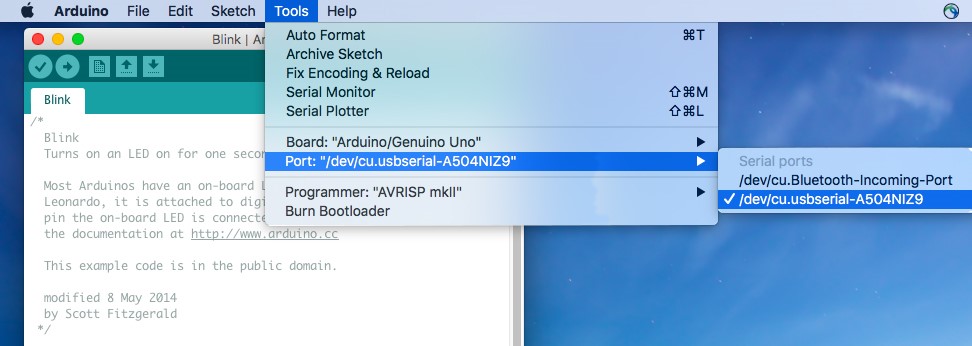
then port, The port here (/dev/tty.usbserial-A504NIZ9) may be different from the Arduino board name (Uno, etc.).
Click to Upload icon, if "Done uploading" appears at the bottom of the window, it means the sketch has been successfully uploaded. And if you see the pin 13(L) LED starts to flicker, it means the code has been successfully run.
