Robot Speed Measuring Module
Introduction
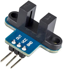
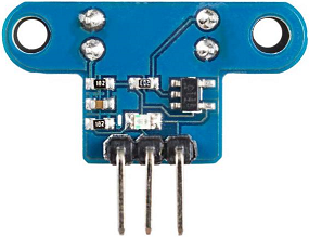
The speed measuring module is usually used on smart cars and it is equiped with slot type photoelectric sensors. The module outputs high level signals as soon as the non-transparent material goes through the slot. Due to the application of Schmitt trigger, the signal can be stable after the pulse getting debounce. Moreover, the module is commonly used in the measurement of rotation speed of the car and the distance to the obstacle.
Features
- Chip: 74HC14D;
- Working Voltage: 3.3V ~5V;
- Output Mode: Digital Output Signal (Pulse Signal);
- Detection Mode: Infrared Signal Interrupt;
- Detection Signal: Obstacles detected, high level is output; nothing is detected or the obstacle is out of the detection range, low level is output.
- Status indicator: Turn off when the ray is interrupted; otherwise, turn on.
Introduction of Pins
OUT:Switch signal output
GND:Connected to the anode of power supply (3.3V-5V)
VCC:Connected to the cathode of power supply
Principle
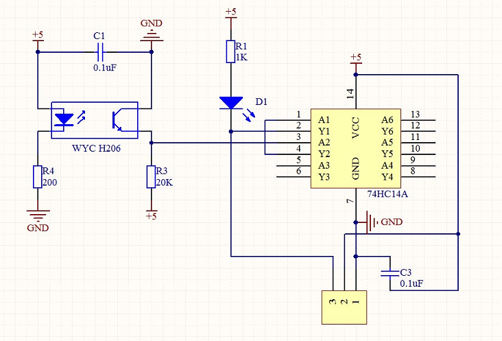
VCC and GND connected, the module indicator light is on. When there is no occlusion over the module slot, receiving tube is in conducting and the module OUT outputs high level;
with an occlusion, OUT outputs low level and the signal indicator light turns off. The module OUT can be connected with relay to realize a function of limit switch and it can also form a annunciator by wiring up an active buzzer.
OUT port can be directly connected to IO port of MCU. Generally it is connected with external interrupt to detect the existence of the occlusion over the sensor, for example, using an encoding disk to measure the motor speed.
Distance Measuring:
Speed measurement sensor outputs pulse signal and one pulse interrupts once; During conducting, the infrared ray outputs low level, thus we set the interrupt to the low - level triggered mode.
Generally, there are so many grids on the encoding disk. No matter how many the grids are, the working principle is identical. For example, there are 10 grids on the encoding disk. Every time the motor rotates one round, the ray conducts 10 times and the external low level is triggered ten times.
Following the above thinking, we know one circle the motor rotates will cause ten times of interrupt, so we can calculate the times of interrupt and let it be divided by 10 to get the motor rotation times. In the same way, we can calculate the car’s driving distance with wheel perimeter.
Speed Measuring
With the guidance of the distance measuring principle, we choose to calculate the times of external interrupt per second with MCU timer. For example, if there are 20 times of external interrupt every second, we can know that the wheel rotates two circles per second. Then it is not difficult to calculate the speed with the wheel peripheral.
Experimental Procedures for Arduino
Step 1: Connect the circuit:
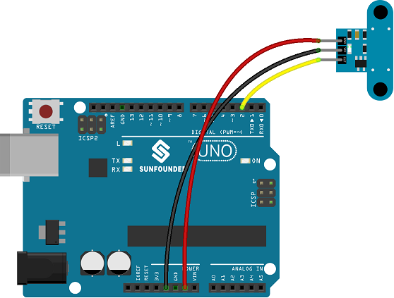
Step 2: Compile and upload the code.
int inputPin = 2; // Connect sensor to input pin 2

void setup() {

Serial.begin(9600); // Init the serial port

pinMode(inputPin, INPUT); // declare Micro switch as input

}

void loop(){

int val = digitalRead(inputPin); // read input value

if (val == LOW) { // check if the input is HIGH

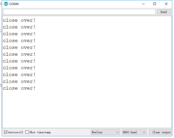
Serial.println("close over!");

} else {


}

delay(50);

}
