MultiWii GUI Parameter Configuration
MultiWii GUI Parameter Configuration
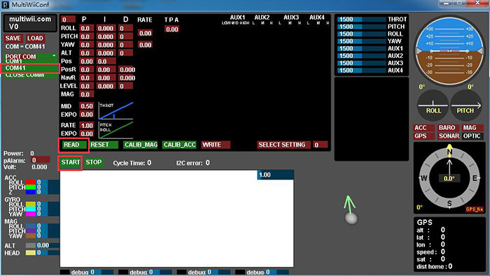
Select an Italic textoption under PORT COM to select a proper serial port (here it is COM41), then the buttons START and READ will turn green. Click START to show the data curve. Finally, click READ to load the default PID parameters.
- Figure 1
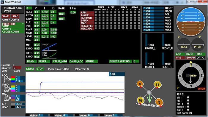
If everything goes well, you will see the following interface:
- Figure 2
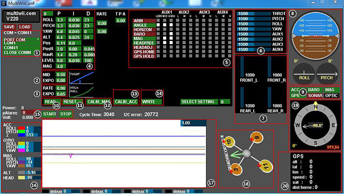
Next, let's get to know the meaning of each area in GUI, as shown in figure 3:
- Figure 3
- Serial Port Selection
- Throttle Curve Setting
- Remote Control Curve Setting
- PID Parameters Adjustment
- Flight Mode Setting
- Output Channels for Remote Control
- Motor Output
- Attitude Angles
- Activation State for Sensors
- Read Parameters
- Reset Parameters
- Calibrate Magnetometer
- Calibrate Accelerometer
- Write Parameters
- Start to Output or Stop Outputting Sensor Data
- Sensor Data
- Output Curve of Sensors
- 3D Diagram for Quadcopter
- Direction Angle
- GPS Output Data
That's all for introduction to the MultiWii platform. Next, let’s configure the related parameters on the GUI.
- Calibrating Accelerometer
Place the flight control or the quadcopter onto a horizontal surface, like the floor in your house. Connect your computer and the flight control with FTDI. Run GUI, and click CALIB_ACC. Then you will find the output value of the pitch, roll, and Z axes of ACC will be changed into about 0, 0, 512 respectively. This means calibration is completed. - Calibrating Magnetometer
After calibrating the accelerometer, click CALIB_MAG, and you will find the indicator light of the flight control board is blinking. Now, you have thirty seconds to spin the flight control or quadcopter 360 degrees around the three axes (pitch, roll, and Z). It would be better to spin it around each axis two circles in case insufficient spinning. Test it with a compass after calibration. - Adjusting PID Parameters
Hover the cursor on the PID parameter you want to adjust. Press and hold the left mouse button and move the mouse right and left to adjust it. Actually, since the aircraft can fly well with default parameters, you do not need to adjust the parameters at the beginning. - Adjusting Throttle Curve
You may find it very difficult to hover the quadcopter when testing because it is challenging to control the throttle flexibly. When you pull the throttle rocker arm, the aircraft will fly very high; when you push the throttle down, the copter will fall sharply onto the ground. To solve the issue, you need to adjust the throttle curve. For example, set MID as 0.4, EXPO as 0.7. For the remote control curve, just leave the default parameters. - Selecting Flight Mode
ARM: Selecting the lock/unlock mode for the flight control
ANGLE: Self-stabilization mode
HORIZON: Horizontal flight mode
BARO: Height keeping by barometric pressure
MAG: Direction keeping
HEADFREE: Headless Mode
HEADADJ: Head Adjustment Mode
GPS HOME: One Key to Return
GPS HOLD: Fixing Point
The two- or three-stage switch signal of the remote control goes into the MODE port of the flight control, and then is displayed as AUX1, AUX2, AUX3, and AUX4. Toggle the switch, and you will see the slider of AUX1, AUX2, AUX3, and AUX4 accordingly on the GUI. Here you need to use it to control the state of the sensors. The small grey check means the current setting is invalid. Click on the check and it will turn to white, which means it becomes valid.
As shown in Figure 4, there are three columns of small checks under each of AUX1, AUX2, AUX3, and AUX4, which represent three states of the three-stage switch. When the switch is toggled to LOW, MID, or HIGH, the corresponding check will be white. For example, click on the following eight checks, and click WRITE to save the change.
- Figure 4
When you push the switch of AUX1 to the lowest, the slider of AUX1 will be at column LOW, ANGLE will turn green (means activated), and the flight mode of the flight control will set to self-stabilization mode. When you push it to the middle, the slider of AUX1 will be at column MID and the flight mode will be self-stabilization mode + headless mode. When you pull it to the highest, the slider of AUX1 will be at High and the flight mode will be self-stabilization mode + headless mode + fixed height. The way to set other modes is similar to this. You just need to understand the meaning of each flight mode and slide to LOW, MID, or HIGH.


