Difference between revisions of "GY-271 HMC5883L 3-Axis Magnetic Electronic Compass Module"
| Line 24: | Line 24: | ||
<li>Measuring Range: ±1.3-8 Gauss.</li> | <li>Measuring Range: ±1.3-8 Gauss.</li> | ||
<ol> | <ol> | ||
| − | + | ||
| − | + | == '''Introduction of Pins''' == | |
| − | + | {| | |
| − | + | Introduction of Pins | |
| − | + | |- | |
| − | + | |VCC |Connected to the anode of the power supply (3~5v) | |
| − | + | |- | |
| + | |GND |Connected to the cathode of the power supply | ||
| + | |- | ||
| + | |SCL |I²C clock | ||
| + | |- | ||
| + | |SDA |I²C data | ||
| + | |- | ||
| + | |DRDY |Interrupting pin for data preparation, DRDY is pulled up inside and keeps the low level for 250μsec when the data are on the output register. | ||
| + | |||
| + | |} | ||
Revision as of 06:01, 24 September 2019
Introduction

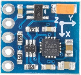
The Compass Module is designed for low-field magnetic sensing with a digital interface and perfect to give precise heading information. This compact sensor fits into small projects such as UAVs and robot navigation systems. The sensor converts any magnetic field to a differential voltage output on 3 axes. This voltage shift is the raw digital output value, which can then be used to calculate headings or sense magnetic fields coming from different directions.
Main Features
1. Gold plating PCB, applying machine welding technology, superb technique and reliably quality guarantee! 2. Name: HMC5883L Module (Triaxial Magnetic Field Module); 3. Type: GY-271; 4. Used Chip: HMC5883L; 5. Power Supply: 3~5V; 6. Communication Mode: Standard IIC communicating protocol; 7. Measuring Range: ±1.3-8 Gauss.
Main Features
- Gold plating PCB, applying machine welding technology, superb technique and reliably quality guarantee!
- Name: HMC5883L Module (Triaxial Magnetic Field Module);
- Type: GY-271;
- Used Chip: HMC5883L;
- Power Supply: 3~5V;
- Communication Mode: Standard IIC communicating protocol;
- Measuring Range: ±1.3-8 Gauss.
Introduction of Pins
| Connected to the anode of the power supply (3~5v) |
| Connected to the cathode of the power supply |
| I²C clock |
| I²C data |
| Interrupting pin for data preparation, DRDY is pulled up inside and keeps the low level for 250μsec when the data are on the output register. |