PCA9685 16-Channel 12 Bit I2C Bus PWM Driver
Contents
Introduction
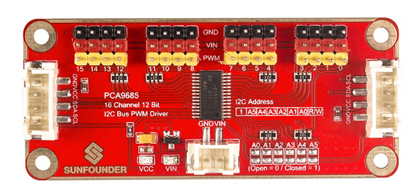
The PCA9685 is an I2C-bus controlled 16-channel LED controller optimized for Red/Green/Blue/Amber (RGBA) color backlighting applications. Each LED output has its own 12-bit resolution (4096 steps) fixed frequency individual PWM controller that operates at a programmable frequency from a typical of 24Hz to 1526Hz with a duty cycle that is adjustable from 0 % to 100 % to allow the LED to be set to a specific brightness value. All outputs are set to the same PWM frequency.
This PWM Servo Driver uses the chip PCA9685 for control. With only 2 pins, it can drive 16 servos, which greatly reduces the I/O occupation. In addition, you can connect up to 62 driver boards in a cascading way, thus amazingly driving 992 servos in total.
Features
>A PWM Driver with I2C interface
>Controls 16 PWM output channels with only 2 pins, and connects 62 >driver boards at most in a cascading way to drive up to 992 PWM output channels
>The base of pins on the board to connect servo wires are paint in 3 colors for easy recognition, so you can plug in the wires correctly at the first sight by color.
>Supports max 12V for external power supply; with a power indicator 12-bit resolution for each output - for servos, that means about 4us resolution at 60Hz update rate
>Frequency: 40-1000Hz
>Channel number: 16 channel
>Resolution: 12 bit
>Voltage: DC 12V (Max)
>Size: 74 x 32 mm
Principle
The driver module uses the PCA9685 chip as control and can output 16 channels of PWM signal. You can program the control chip to set the PWM frequency and duty cycle of each channel so as to accurately control servos. The turn-on time of each LED driver output and the duty cycle of PWM can be controlled independently using the LEDn_ON and LEDn_OFF registers.
If we set the time of LED_ON as 409, the time span for LED_OFF would be 1228, and the duty cycle of PWM be: (1228-409/4096) x 100% = 20%.

How a servo works: PWM signals go into the signal demodulation circuit through the receiving channel, so to generate a DC bias voltage. It will then be compared with the voltage of the potentiometer, and thus a voltage gap is obtained and input into the motor driver IC to drive the motors to rotate clockwise or anticlockwise. When the speed reaches to a certain number, it will drive the potentiometer R to rotate by the cascaded reduction gear, until the gap is reduced to 0 and the servo stops spinning. A servo is controlled by PWM signals, and the change of duty cycle control that of the position the servo rotates to.
Control Servos with Arduino
Control with one driver board
Control the servo rotate from 0 to 180 degrees
Components
- 1 x PCA968 servo driver module
- 1 x Arduino Uno board
- 1 x Servo
- 1 x 18650 battery holder
- 2 x 18650 Lithium battery
- Several jump wires
Step 1. Wiring
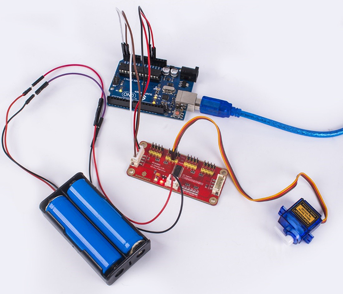
Since the servo consumes a large quantity of power when in work, to provide adequate capacity, please use an extra power supply for the module.
Connect the devices:
| Independent Power Source | PCA9685 16-Channel 12 Bit I2C Bus PWM Driver |
| VCC | VIN |
| GND | GND |
Connect Arduino Uno and PCA9685 driver:
| Arduino Uno | PCA9685 16-Channel 12 Bit I2C Bus PWM Driver |
| 5V | VCC |
| GND | GND |
| SDA(A4) | SDA |
| SCL(A5) | SCL |
Connect the servo and PCA9685 driver (OK to connect one PWM output, or less than 16 servos):
| Servo | PCA9685 16-Channel 12 Bit I2C Bus PWM Driver |
| Orange wire | PWM |
| Red wire | VIN |
| Brown wire | GND |
See the figure as below for the wiring:
Step 2. Install the library
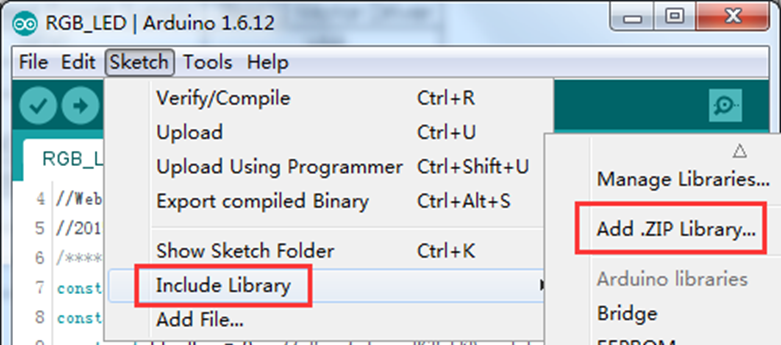
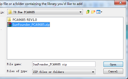
Open the Arduino software, and select Sketch -> Include Library ->Add .ZIP Library.
Step 3. Open an example sketch
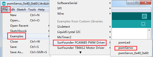
Upload the sketch to the board. Then you can see the servo rotates from 0 to 180 degrees and back from 180 to 0 degree repeatedly.
Cascading multiple driver modules
In this experiment, we'll cascade 2 servo driver modules. For the application of more modules, please refer to the principle. Based on the experiment previously, you need at least two servos - each driver module connects one.
Addressing the Boards
Each board in the chain must be assigned with a unique address. This is done with the address jumpers on the upper right edge of the board. The I2C base address for each board is 0x40. The binary address that you program with the address jumpers is added to the base I2C address. To program the address offset, use a drop of solder to bridge the corresponding address jumper for each binary '1' in the address.
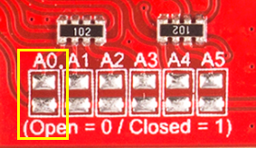

Board 0: Address = 0x40 Offset = binary 00000 (no jumpers required)
Board 1: Address = 0x41 Offset = binary 00001 (bridge A0 as in the photo above)
Board 2: Address = 0x42 Offset = binary 00010 (bridge A1)
Board 3: Address = 0x43 Offset = binary 00011 (bridge A0 & A1)
Board 4: Address = 0x44 Offset = binary 00100 (bridge A2)
State the objects
After assigning the address, you need to add an instruction to select the driver module that accepts the command (for example, here the I2C address of the second driver module is 0x60):
void loop() {
  setAddr(0x40);    // select the 0x40 board
  channel_all();

  setAddr(0x60);    // select the 0x60 board
  channel_all();
}
Connect the devices and run the code
| Arduino Uno | PCA9685 1 | PCA9685 2 |
| 5V | VCC | VCC |
| GND | GND | GND |
| SDA(A4) | SDA | SDA |
| SCL(A5) | SCL | SCL |
For wiring of the independent power supply and the servo, refer to the previous wiring for control with one driver board.
Open the Arduino IDE and open an example:
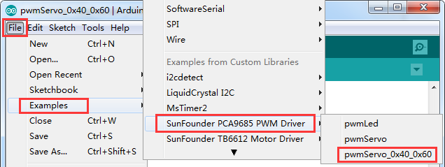
Now you can see the servo 1 rotates from 0 to 180 degrees and back from 180 to 0 degree, and next the servo 2 repeats this cycle.
Control Servos with Raspberry Pi
Control a servo and LED with one driver board
Step 1. Create your project:
Log into the Raspberry Pi via ssh, and clone the PCA9685 repository from Github:
git clone https://github.com/sunfounder/SunFounder_PCA9685.git
After clone is done, you'll have a Python package of PCA9685 and can then import it into your Python program for use.
PCA9685 communicates with Raspberry Pi via I2C. Therefore you need to enable the I2C of the Raspberry Pi:
sudo raspi-config
Select Advanced Options -> I2C and yes.
Check a simple example:
1. Create a directory:
mkdir test_PCA9685/
2. Copy the package to the directory:
cd test_PCA9685
cp -r /home/pi/SunFounder_PCA9685 ./
3. Create the code file:
touch test_led.py
touch test_servo.py
So now the structure of your program should be like this:
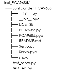
It means there are 1 directory and 11 files.
Only it be this way, you can correctly import the package.
Now let's see how to control the LED and servo.
Use PCA9685 to control LED
Step 2. Wiring
See the pin arrangement of the Raspberry Pi below:
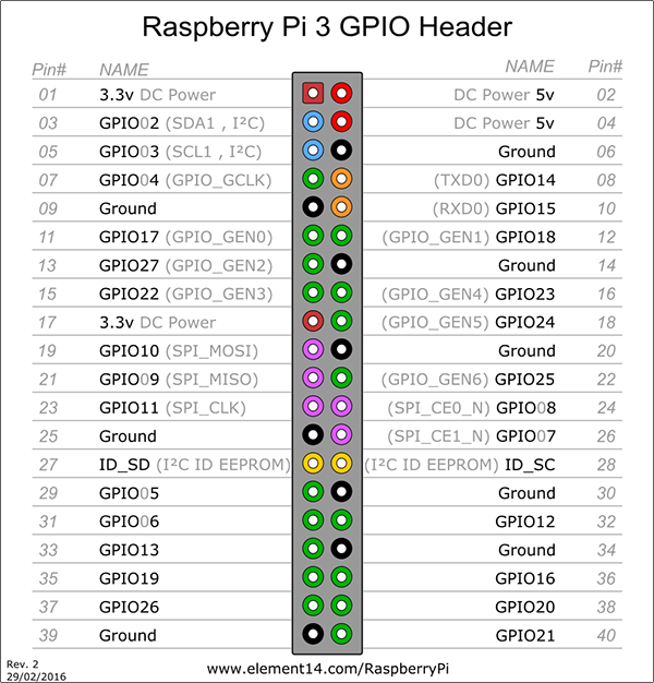
Connect the Raspberry Pi and the driver module:
| Raspberry Pi | PCA9685 16-Channel 12 Bit I2C Bus PWM Driver |
| 5V | VCC |
| GND | GND |
| SDA | SDA |
| SCL | SCL |
Connect the driver module and LED:
| LED | Resistor (220Ω) | PCA9685 16-Channel 12 Bit I2C Bus PWM Driver |
| '+' of LED | —— | PWM |
| '-' of LED | One end of the resistor | —— |
| —— | The other end of the resistor | GND |
Step 3. Write the code for LED
nano test_led.py
Write the following code [applies to the driver module to which no address is assigned yet, namely module not soldered with a default address of 0x40 because after A0 is soldered an address will be assigned: pwm = PCA9685.PWM(1,address=0x60)]:
import time
from SunFounder_PCA9685 import PCA9685

pwm = PCA9685.PWM() # address is 0x40 by default
pwm.frequency = 60

while True:
        for i in range(0, 4095, 10):
                print i
                pwm.write_all_value(0, i)
                time.sleep(0.0001)
        for i in range(4095, -1, -10):
                print i
                pwm.write_all_value(0, i)
                time.sleep(0.0001)
Press Ctrl+X and a prompt of Save or not will be popped up. Select Y to save, and Enter to exit.
Type in the command to run the example:
python test_led.py
In the test code, all channels are used for PWM output to adjust the brightness of the LED.
Now you can see the breathing LED - mimicking the breath of human being. Press Ctrl+C if you want it to stop.
Use PCA9685 to control servo
Remove the LED and keep the wiring between the Raspberry Pi and the driver module unchanged.
Connect the servo - to a separate power supply since it consumes large currents.
Connect an independent power supply:
| Independent Power Source | PCA9685 16-Channel 12 Bit I2C Bus PWM Driver |
| VCC | VIN |
| GND | GND |
Connect the servo:
| Servo | PCA9685 16-Channel 12 Bit I2C Bus PWM Driver |
| Orange wire | PWM |
| Red wire | VIN |
| Brown wire | GND |
Step 4. Write the code for servo (under /test_PCA9685, namely, pi@raspberrypi:~/test_PCA9685 $)
nano test_servo.py
Type in the code:
import time
from SunFounder_PCA9685 import Servo

myservo = []
for i in range(0, 16):
        myservo.append(Servo.Servo(i))  # channel 1
        print 'myservo%s'%i

while True:
        for i in range(0, 180, 5):
                print i
                for channel in range(0, 16):
                        myservo[channel].write(i)
                        print '   channel%s'%channel
                time.sleep(0.1)
        for i in range(180, 0, -5):
                print i
                for channel in range(0, 16):
                        myservo[channel].write(i)
                        print '    channel%s'%channel
                time.sleep(0.1)
Enter the command to run the example:
python test_servo.py
Now you can see the servo 1 rotates from 0 to 180 degrees and back from 180 to 0 degree, and next the servo 2 repeats this cycle.Press Ctrl+C if to stop.
Control servos and LEDs by cascading multiple driver boards
After assigning the address, you only need to add a parameter of address in the instance:
pwm1 = PCA9685.PWM(1, address=0x40) # Use the PWM class
pwm2 = PCA9685.PWM(1, address=0x60) # i2c address: 0x60
myservo1 = Servo.Servo(1, address=0x40) # Use the Servo class
myservo2 = Servo.Servo(1, address=0x60) # i2c address: 0x60
Use the PWM class to adjust the LED brightness
Connect an LED to each of the two driver modules (any PWM output port)
Modify the previous file test_led.py: pi@raspberrypi:~/test_PCA9685 $
nano test_led.py
Then the code should be like this:
import time
from SunFounder_PCA9685 import PCA9685

pwm1 = PCA9685.PWM(1, 0x60)
pwm2 = PCA9685.PWM(1, 0x40)
pwm1.frequency = 60
pwm2.frequency = 60

while True:
        for i in range(0, 4095, 10):
                print "pwm1 0x40: ", i
                pwm1.write_all_value(0, i)
                time.sleep(0.0001)
        for i in range(4095, -1, -10):
                print "pwm1 0x40: ", i
                pwm1.write_all_value(0, i)
                time.sleep(0.0001)
        for i in range(0, 4095, 5):
                print "pwm2 0x60: ", i
                pwm2.write_all_value(0, i)
                time.sleep(0.0001)
        for i in range(4095, -1, -10):
                print "pwm2 0x60: ", i
                pwm2.write_all_value(0, i)
                time.sleep(0.0001)
Type in the command to run the example: pi@raspberrypi:~/test_PCA9685 $
python test_led.py
Now you can see two breathing LEDs - breathe one by one, repeatedly. Press Ctrl+C if to stop.
Use the Servo class for servo driver
Modify the file test_servo.py: pi@raspberrypi:~/test_PCA9685 $
nano test_servo.py
The code should be:
import time
from SunFounder_PCA9685 import Servo

myservos1 = []
myservos2 = []

delay = 0.001

for i in range(0, 16):
        myservos1.append(Servo.Servo(channel=i, address=0x40))  # servos connect to 0x40 i2c board
        myservos2.append(Servo.Servo(channel=i, address=0x60))  # servos connect to 0x60 i2c board
        print 'myservo%s'%i

while True:
        for i in range(0, 180, 5):
                print i
                for channel in range(0, 16):
                        myservos1[channel].write(i)
                        time.sleep(delay)
                        myservos2[channel].write(i)
                        time.sleep(delay)
                        print '   channel%s'%channel
                time.sleep(0.1)
        for i in range(180, 0, -5):
                print i
                for channel in range(0, 16):
                        myservos1[channel].write(i)
                        time.sleep(delay)
                        myservos2[channel].write(i)
                        time.sleep(delay)
                        print '    channel%s'%channel
                time.sleep(0.1)
Type in the command to run the code: python test_servo.py Now you can see the servo 1 rotates from 0 to 180 degrees and back from 180 to 0 degree, and next the servo 2 repeats this cycle, continuing circularly. Press Ctrl+C if to stop.