Difference between revisions of "Light Follower Module"
(→Module Test) |
(→Resources) |
||
| Line 66: | Line 66: | ||
=='''Resources'''== | =='''Resources'''== | ||
| − | [ | + | [http://wiki.sunfounder.cc/index.php?title=File:COM_SunFounder_Light_Follower_ModuleREV1.0.pdf Light_Follower_Module schematic][[File:PDF.jpg]]<br> |
| − | [ | + | [http://wiki.sunfounder.cc/index.php?title=File:STM8S003_datasheet.pdf STM8S003_datasheet][[File:PDF.jpg]]<br> |
Revision as of 07:13, 20 March 2017
Introduction
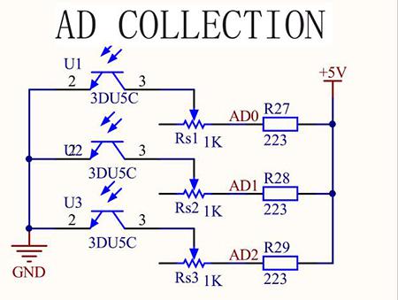
Phototransistor, or photo triode, is a photoelectric conversion component that senses the light intensity. The stronger light, the larger currents, and better conductivity of the triode.
Based on this principle, we use it for light following. It works by converting the conductivity to voltage output, which means the stronger light shone on it, the smaller voltage output. Then convert the voltage into digital values by the A/D converter on the MCU. And we can tell the light intensity then by this value.
The module can be used to sense the ambient luminance. The blue potentiometer is to adjust the sensitivity – you can change it to adapt to specific circumstances. There are two mounting holes of 3mm diameter on the module for easy installation on your robot.
All in all, this Light Follower Module is a perfect choice for you to achieve a light following project!
Features
1.A three-way light following module uses the MCU STM8S003 as the controller and three 3du5c phototransistors for sensors
2.Sensitivity of the transistor adjustable by the blue potentiometer
3.Equipped with corresponding indicating lights (8 LEDs) – the strong light, the more brightened LEDs
4.Comes with anti-reverse plug and 5-pin anti-reverse cable, for easy and stable wiring
5.Working voltage: 5V; PCB size: 124 x 30 mm
Module Test
Step 1. Install the Arduino IDE in your computer. For detailed steps, refer to http://wiki.sunfounder.cc/index.php?title=Install_Arduino_Software
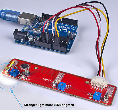
Step 2. Connect the Arduino Uno board. Wiring:
- Light Follower Module ------ Arduino Uno
- 5V ----------------------- VCC
- GND ----------------------- GND
- AD0 ----------------------- A0
- AD1 ----------------------- A1
- AD2 ----------------------- A2
- Light Follower Module ------ Arduino Uno
Step 3. Upload the sketch. Copy the following code to arduino IDE ,before clicking the Upload (right arrow button) icon, set the Port and Board under Tools menu.
Test Code
void setup() {
 // put your setup code here, to run once:
 Serial.begin(9600);
}
void loop() {
 // put your main code here, to run repeatedly:
 Serial.print("AD0:");
 Serial.print(analogRead(A0));
Serial.print(" \t ");
 Serial.print("AD1:");
 Serial.print(analogRead(A1));
Serial.print(" \t ");
 Serial.print("AD2:");
 Serial.println(analogRead(A2));
 delay(500);
}
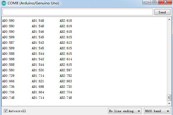
Step 4. Check the value on Serial Monitor. Click the icon ![]() at the right upper corner. When any of the photo-sensors on the module approaches the light source, the corresponding AD value will decrease; once it moves away from the light, the value will increase, as shown below:
at the right upper corner. When any of the photo-sensors on the module approaches the light source, the corresponding AD value will decrease; once it moves away from the light, the value will increase, as shown below:
At the same time you can observe the three columns of indicator LEDs on the module, each column for one photo-sensor. When any of the sensors approaches the light source, the corresponding column of LEDs will brighten; the stronger light, the more LEDs on. When the sensor gets away from the source, the LEDs will dim out. If the indicators are on when there's no light source, you can adjust the potentiometers Rs1, Rs2 and Rs3 corresponding to the three sensors to dim the light. After the calibration, the sensors then can achieve optimal effect.


